
Page 264 - Phase-Locked Loops Design, Simulation, and Applications
P. 264
MIXED-SIGNAL PLL APPLICATIONS PART 1: INTEGER-N FREQUENCY
SYNTHESIZERS Ronald E. Best 156
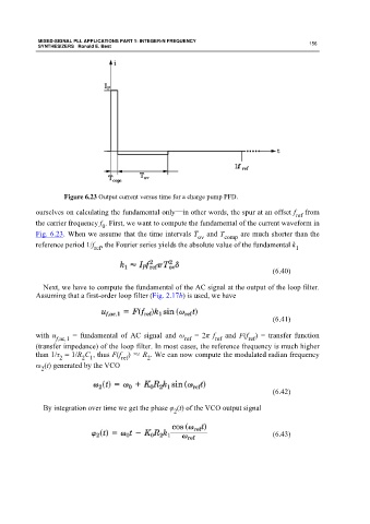
Figure 6.23 Output current versus time for a charge pump PFD.
ourselves on calculating the fundamental only—in other words, the spur at an offset f from
ref
the carrier frequency f . First, we want to compute the fundamental of the current waveform in
0
Fig. 6.23. When we assume that the time intervals T and T are much shorter than the
ov comp
reference period 1/f , the Fourier series yields the absolute value of the fundamental k
1
ref
(6.40)
Next, we have to compute the fundamental of the AC signal at the output of the loop filter.
Assuming that a first-order loop filter (Fig. 2.17b) is used, we have
(6.41)
with u f,ac,1 = fundamental of AC signal and ω = 2π f and F(f ) = transfer function
ref
ref
ref
(transfer impedance) of the loop filter. In most cases, the reference frequency is much higher
than 1/τ = 1/R C , thus F(f ) ≈ R . We can now compute the modulated radian frequency
2 2 1 ref 2
ω (t) generated by the VCO
2
(6.42)
By integration over time we get the phase φ (t) of the VCO output signal
2
(6.43)