
Page 266 - Phase-Locked Loops Design, Simulation, and Applications
P. 266
MIXED-SIGNAL PLL APPLICATIONS PART 1: INTEGER-N FREQUENCY
SYNTHESIZERS Ronald E. Best 157
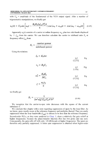
with U = amplitude of the fundamental of the VCO output signal. After a number of
0
trigonometric manipulations, we finally get
(6.45)
Apparently u (t) consists of a carrier at radian frequency ω , plus two side-bands displaced
2 0
by ± f from the carrier. We can therefore calculate the carrier to sideband ratio S at
1
ref
frequency offset f from
ref
Using the relations
[cf. Eq.
(2.27)]
(cf. Fig.
2.17b)
[cf. Eq.
(3.23)]
[cf. Eq.
(3.23)]
we finally get
(6.46)
We recognize that the carrier-to-spur ratio decreases with the square of the current
imbalance δ.
We conclude this chapter with a note regarding suppression of spurs by the loop filter. As
we know, spurs mostly occur at the reference frequency and multiples thereof. They are easily
suppressed when the loop bandwidth (f ) is chosen to be less than the reference frequency.
3dB
Second-order PLLs, as they were analyzed in Chap. 3, show a relatively flat gain rolloff at
higher frequencies, because the phase-transfer function H(s) has two poles and one zero.
Consequently, the gain rolls off with only −20 dB/decade at higher frequencies. The spurs are
therefore only partially suppressed. A better spur suppression is obtained when higher-order