
Page 270 - Phase-Locked Loops Design, Simulation, and Applications
P. 270
MIXED-SIGNAL PLL APPLICATIONS PART 2: FRACTIONAL-N FREQUENCY 160
SYNTHESIZERS Ronald E. Best
120 kHz, and up. Let’s now think about a divide-by-N counter that is not only able to
scale down by 10, 11, and 12, but by 10.0, 10.1, 10.2, and so on. If such a down scaler
were realizable, we could create output frequencies of 10 · f , 10.1 · f , 10.2 · f ,
ref ref ref
and so forth. Still using f = 10 kHz, we now would be able to create the frequencies 100
ref
kHz, 101 kHz, 102 kHz, and so on. To obtain a channel spacing of 10 kHz, we now could
choose f = 100 kHz, which is the tenfold of the “old” reference frequency! Doing so,
ref
the natural frequency could also be increased by a factor of 10, and the loop would be ten
times as fast as the “old” one.
This is one of the ideas behind the so-called fractional-N frequency synthesizer. Other
reasons lead to the design of fractional-N synthesizers, too, of course: there could be a
demand to produce signals whose frequency can be any multiple of a precise frequency
standard—for example, 123.45 kHz, 146.73 kHz, and so on. Signal generators are an
example for those applications.
Since a down scaler is always a digital circuit, it certainly can’t divide by fractional
numbers like 10.1 or 10.2, only by integer numbers like 10 or 11. Dividing by 10.5, for
example, becomes possible, however, if the divide-by-N counter is made to scale down
alternately by 10 and by 11. On average, this counter effectively divides the input
frequency by 10.5. Dividing by 10.1 also becomes realizable, if the counter divides by 11
in one cycle within a sequence of 10 cycles, and by 10 in the remaining 9 cycles.
Switching the divider ratio of a down scaler is simple to realize, but this technique
inevitably leads to phase jitter, as will be demonstrated by the following example.
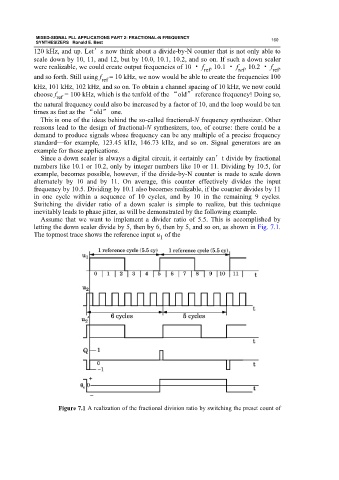
Assume that we want to implement a divider ratio of 5.5. This is accomplished by
letting the down scaler divide by 5, then by 6, then by 5, and so on, as shown in Fig. 7.1.
The topmost trace shows the reference input u of the
1
Figure 7.1 A realization of the fractional division ratio by switching the preset count of