
Page 76 - Phase-Locked Loops Design, Simulation, and Applications
P. 76
MIXED-SIGNAL PLL ANALYSIS Ronald E. Best 54
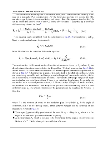
The mathematical model depends somewhat on the types of phase detectors and loop filters
used in a particular PLL configuration. For the following analysis, we assume the PLL
contains a type 1 phase detector (multiplier) and a type 1 loop filter (passive lead-lag filter). It
can be shown that the behavior of the PLL in the unlocked state is described by a nonlinear
differential equation of the form 4
(3.42)
This equation can be simplified. First, the substitutions of Eq. (3.13) are made for τ and τ .
1
2
Next, in most practical cases, the inequality
(3.43)
holds. This leads to the simplified differential equation
(3.44)
The nonlinearities in this equation stem from the trigonometric terms sin θ and cos θ . As
e
e
already stated, there is no exact solution for this problem. We find, however, that Eq. (3.44) is
almost identical to the differential equation of a somewhat special mathematical pendulum, as
shown in Fig. 3.7. A beam having a mass M is rigidly fixed to the shaft of a cylinder, which
can rotate freely around its axis. A thin rope is attached at point P to the surface of the cylinder
and is then wound several times around the latter. The outer end of the rope hangs down freely
and is attached to a weighing platform. If there is no weight on the platform, the pendulum is
assumed to be in a vertical position with φ = 0. If some weight G is placed on the platform,
e
the pendulum will be deflected from its quiescent position and will eventually settle at a final
deflection angle φ . The dynamic response of the pendulum can be calculated by Newton’s
e
third law
(3.45)
where T is the moment of inertia of the pendulum plus the cylinder, φ is the angle of
e
deflection, and J is the driving torque. Three different torques can be identified in the
i
mechanical system of Fig. 3.7:
■ The torque J generated by gravitation of the mass M; J = −Mag sin φ , where a is the
E E e
length of the beam and g is acceleration due to gravity.
■ A friction torque J , which is assumed to be proportional to the angular velocity (viscous
R
friction); , where ρ is the coefficient of friction.