
Page 97 - Phase-Locked Loops Design, Simulation, and Applications
P. 97
MIXED-SIGNAL PLL ANALYSIS Ronald E. Best 66
and the output signal by
where “rect” denotes a symmetrical square wave signal.
Using Eq. (2.16), the phase detector will deliver an output signal given by
The higher-frequency terms can be discarded because they will be almost entirely filtered
out by the loop filter. At the output of the loop filter, there appears a signal u (t) given by
f
This is an AC signal that causes a frequency modulation of the VCO.
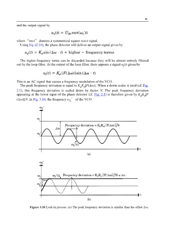
The peak frequency deviation is equal to K K |F(Δω)|. When a down scaler is used (cf. Fig.
d 0
2.1), this frequency deviation is scaled down by factor N. The peak frequency deviation
appearing at the lower input of the phase detector (cf. Fig. 2.1) is therefore given by K K |F
d 0
(Δω)|/N. In Fig. 3.10, the frequency ω ′ of the VCO
2
Figure 3.10 Lock-in process. (a) The peak frequency deviation is smaller than the offset Δω;