
Page 18 - Photodetection and Measurement - Maximizing Performance in Optical Systems
P. 18
Photodetection Basics
Photodetection Basics 11
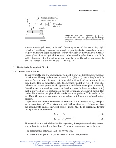
Refractive index n=3.5
Normal reflectivity
( n - 1 ) 2
R = n + 1 = 31%, unless
AR-coated
Anode
p
i-layer
Figure 1.6 The high reflectivity of an air/
n semiconductor interface, given by the Fresnel
equations, stops some incident light reaching the
Cathode junction.
a wide wavelength band, with each detecting some of the remaining light
reflected from the previous one. Alternatively, surface textures can be arranged
to give a similarly high absorption. Where the light is incident from a trans-
parent glass block or optical fiber, even index matching the fiber to the diode
with a transparent gel or adhesive can roughly halve the reflection losses. To
see this, substitute n = 1.5 for the “1” in Fig. 1.6.
1.7 Photodiode Equivalent Circuit
1.7.1 Current source model
To conveniently use the photodiode, we need a simple, didactic description of
its behavior. The equivalent circuit we will use (Fig. 1.7) treats the photodiode
as a perfect source of photocurrent in parallel with an ideal conventional junc-
tion diode. This is compatible with the physical model of Fig. 1.2. The pho-
todetection process generates charge carriers and the internal photocurrent I o.
Note that we have no direct access to I o . All we have is the external current I p
that is provided at the photodiode’s output terminals. We showed earlier that
under illumination the photodiode anode becomes positive. This tends to for-
ward bias the pn-junction, causing internal current flow and a reduced output
current.
Ignore for the moment the series resistance R s, shunt resistance R sh, and par-
asitic capacitance C p . The output current is then given by I o (calculated from
the responsivity values discussed earlier) minus the diode current I d flowing
through the internal diode:
I p = I o - I d (1.5)
I p = I o - I e ( qV d kT - ) 1 (1.6)
s
The second term is called the Shockley equation, the expression relating current
and voltage in an ideal junction diode. The new parameters are as follows:
k: Boltzmann’s constant (1.381 ¥ 10 -23 W·s/K)
T: Absolute temperature (about 300K at room temperature)
Downloaded from Digital Engineering Library @ McGraw-Hill (www.digitalengineeringlibrary.com)
Copyright © 2004 The McGraw-Hill Companies. All rights reserved.
Any use is subject to the Terms of Use as given at the website.