
Page 19 - Photodetection and Measurement - Maximizing Performance in Optical Systems
P. 19
Photodetection Basics
12 Chapter One
Photodiode
terminals
R s A I
I o I d p
"Internal" V d C p R sh Load R L
photocurrent Ideal
generator
diode
K
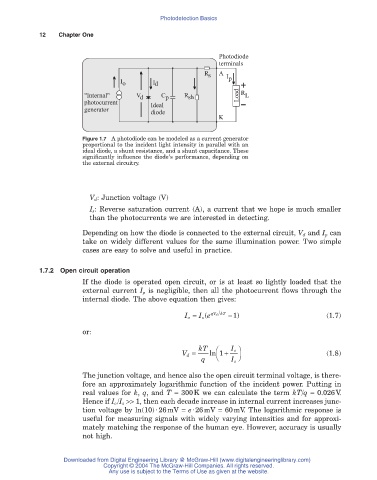
Figure 1.7 A photodiode can be modeled as a current generator
proportional to the incident light intensity in parallel with an
ideal diode, a shunt resistance, and a shunt capacitance. These
significantly influence the diode’s performance, depending on
the external circuitry.
V d : Junction voltage (V)
I s: Reverse saturation current (A), a current that we hope is much smaller
than the photocurrents we are interested in detecting.
Depending on how the diode is connected to the external circuit, V d and I p can
take on widely different values for the same illumination power. Two simple
cases are easy to solve and useful in practice.
1.7.2 Open circuit operation
If the diode is operated open circuit, or is at least so lightly loaded that the
external current I p is negligible, then all the photocurrent flows through the
internal diode. The above equation then gives:
I o = I e ( qV d kT - ) 1 (1.7)
s
or:
Ê
V d = kT ln 1 + I o ˆ (1.8)
q Ë I s ¯
The junction voltage, and hence also the open circuit terminal voltage, is there-
fore an approximately logarithmic function of the incident power. Putting in
real values for k, q, and T = 300K we can calculate the term kT/q = 0.026V.
Hence if I o /I s >> 1, then each decade increase in internal current increases junc-
tion voltage by ln(10)·26mV = e·26mV = 60mV. The logarithmic response is
useful for measuring signals with widely varying intensities and for approxi-
mately matching the response of the human eye. However, accuracy is usually
not high.
Downloaded from Digital Engineering Library @ McGraw-Hill (www.digitalengineeringlibrary.com)
Copyright © 2004 The McGraw-Hill Companies. All rights reserved.
Any use is subject to the Terms of Use as given at the website.