
Page 22 - Photodetection and Measurement - Maximizing Performance in Optical Systems
P. 22
Photodetection Basics
Photodetection Basics 15
2nd Quadrant 1st Quadrant
Current
Dark
Forward bias
Saturation
Current I s
Voltage
V oc
+
- V oc
Max
Increasing power
Light I sc Solar cells
Breakdown Reverse bias I sc
Level
3rd Quadrant 4th Quadrant
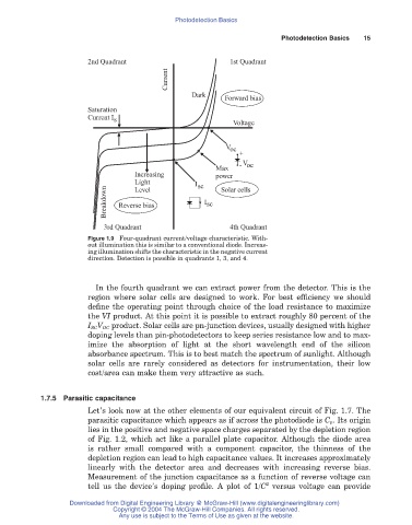
Figure 1.9 Four-quadrant current/voltage characteristic. With-
out illumination this is similar to a conventional diode. Increas-
ing illumination shifts the characteristic in the negative current
direction. Detection is possible in quadrants 1, 3, and 4.
In the fourth quadrant we can extract power from the detector. This is the
region where solar cells are designed to work. For best efficiency we should
define the operating point through choice of the load resistance to maximize
the VI product. At this point it is possible to extract roughly 80 percent of the
I SCV OC product. Solar cells are pn-junction devices, usually designed with higher
doping levels than pin-photodetectors to keep series resistance low and to max-
imize the absorption of light at the short wavelength end of the silicon
absorbance spectrum. This is to best match the spectrum of sunlight. Although
solar cells are rarely considered as detectors for instrumentation, their low
cost/area can make them very attractive as such.
1.7.5 Parasitic capacitance
Let’s look now at the other elements of our equivalent circuit of Fig. 1.7. The
parasitic capacitance which appears as if across the photodiode is C p. Its origin
lies in the positive and negative space charges separated by the depletion region
of Fig. 1.2, which act like a parallel plate capacitor. Although the diode area
is rather small compared with a component capacitor, the thinness of the
depletion region can lead to high capacitance values. It increases approximately
linearly with the detector area and decreases with increasing reverse bias.
Measurement of the junction capacitance as a function of reverse voltage can
2
tell us the device’s doping profile. A plot of 1/C versus voltage can provide
Downloaded from Digital Engineering Library @ McGraw-Hill (www.digitalengineeringlibrary.com)
Copyright © 2004 The McGraw-Hill Companies. All rights reserved.
Any use is subject to the Terms of Use as given at the website.