
Page 27 - Photodetection and Measurement - Maximizing Performance in Optical Systems
P. 27
Amplified Detection Circuitry
20 Chapter Two
Polarity Insulated
switch BNC
Photodiode
I p
+
V Output to scope,
b
3–9V - BNC voltmeter, etc.
Battery V = I R
o
p L
1μF
Switched load resistors R L
100, 1k, 10k, 100k ...
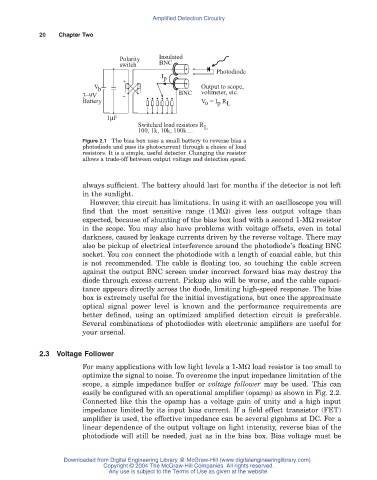
Figure 2.1 The bias box uses a small battery to reverse bias a
photodiode and pass its photocurrent through a choice of load
resistors. It is a simple, useful detector. Changing the resistor
allows a trade-off between output voltage and detection speed.
always sufficient. The battery should last for months if the detector is not left
in the sunlight.
However, this circuit has limitations. In using it with an oscilloscope you will
find that the most sensitive range (1MW) gives less output voltage than
expected, because of shunting of the bias box load with a second 1-MW resistor
in the scope. You may also have problems with voltage offsets, even in total
darkness, caused by leakage currents driven by the reverse voltage. There may
also be pickup of electrical interference around the photodiode’s floating BNC
socket. You can connect the photodiode with a length of coaxial cable, but this
is not recommended. The cable is floating too, so touching the cable screen
against the output BNC screen under incorrect forward bias may destroy the
diode through excess current. Pickup also will be worse, and the cable capaci-
tance appears directly across the diode, limiting high-speed response. The bias
box is extremely useful for the initial investigations, but once the approximate
optical signal power level is known and the performance requirements are
better defined, using an optimized amplified detection circuit is preferable.
Several combinations of photodiodes with electronic amplifiers are useful for
your arsenal.
2.3 Voltage Follower
For many applications with low light levels a 1-MW load resistor is too small to
optimize the signal to noise. To overcome the input impedance limitation of the
scope, a simple impedance buffer or voltage follower may be used. This can
easily be configured with an operational amplifier (opamp) as shown in Fig. 2.2.
Connected like this the opamp has a voltage gain of unity and a high input
impedance limited by its input bias current. If a field effect transistor (FET)
amplifier is used, the effective impedance can be several gigohms at DC. For a
linear dependence of the output voltage on light intensity, reverse bias of the
photodiode will still be needed, just as in the bias box. Bias voltage must be
Downloaded from Digital Engineering Library @ McGraw-Hill (www.digitalengineeringlibrary.com)
Copyright © 2004 The McGraw-Hill Companies. All rights reserved.
Any use is subject to the Terms of Use as given at the website.