
Page 204 - Photonics Essentials an introduction with experiments
P. 204
Optical Fibers and Optical Fiber Amplifiers
198 Advanced Topics
well-defined mechanical structure for automated assembly and splic-
ing of optical fibers. Splicing of fibers is needed to produce spools of
fiber that are sold to fiber optic cable manufacturers. To splice two
fibers, the ends to be joined are cleaved. This is a special process of
breaking a fiber so that its end face is flat. This can be done in the
laboratory by trial and error. If you want to make money, however,
this process must be automatic, and this means that the mechanical
properties of the fiber are consistent from one fiber to another. The
fiber ends are held together and fused by heating. Note that it is the
fiber cores that need to be aligned. Again, you could do this in the
laboratory by sending light down one of the fibers and adjusting the
position of the second fiber for maximum transmission. However, in
a commercial manufacturing process, one relies on the mechanical
alignment of the exteriors of the fibers, and depends on the control
of the core position at the center of the fiber. Control of the fiber core
position to better than 0.5 micron for a 125 micron fiber is now rou-
tine.
These manufacturing processes have made it possible to produce
high volumes of glass fiber with carefully controlled optical, physical,
thermal, and mechanical properties. It is the mastery of these pro-
cesses that have made exploitation of optical fiber telecommunication
a commercial reality.
9.4 Waveguiding in Optical Fibers
Many of the important photonic properties of optical fibers can be un-
derstood knowing only the core diameter and the index difference be-
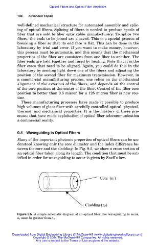
tween the core and the cladding. In Fig. 9.5, we show a cross section of
an optical fiber taken along its length. The condition that must be sat-
isfied in order for waveguiding to occur is given by Snell’s law.
Figure 9.5. A simple schematic diagram of an optical fiber. For waveguiding to occur,
n 1 must be greater than n 2 .
Downloaded from Digital Engineering Library @ McGraw-Hill (www.digitalengineeringlibrary.com)
Copyright © 2004 The McGraw-Hill Companies. All rights reserved.
Any use is subject to the Terms of Use as given at the website.