
Page 209 - Photonics Essentials an introduction with experiments
P. 209
Optical Fibers and Optical Fiber Amplifiers
Optical Fibers and Optical FIber Amplifiers 203
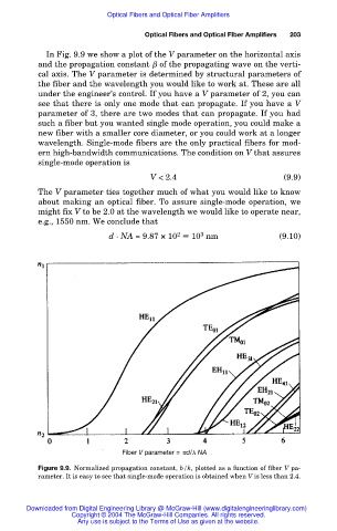
In Fig. 9.9 we show a plot of the V parameter on the horizontal axis
and the propagation constant of the propagating wave on the verti-
cal axis. The V parameter is determined by structural parameters of
the fiber and the wavelength you would like to work at. These are all
under the engineer’s control. If you have a V parameter of 2, you can
see that there is only one mode that can propagate. If you have a V
parameter of 3, there are two modes that can propagate. If you had
such a fiber but you wanted single mode operation, you could make a
new fiber with a smaller core diameter, or you could work at a longer
wavelength. Single-mode fibers are the only practical fibers for mod-
ern high-bandwidth communications. The condition on V that assures
single-mode operation is
V < 2.4 (9.9)
The V parameter ties together much of what you would like to know
about making an optical fiber. To assure single-mode operation, we
might fix V to be 2.0 at the wavelength we would like to operate near,
e.g., 1550 nm. We conclude that
d · NA = 9.87 × 10 10 nm (9.10)
2
3
Fiber V parameter =
d/ NA
Figure 9.9. Normalized propagation constant, b/k, plotted as a function of fiber V pa-
rameter. It is easy to see that single-mode operation is obtained when V is less than 2.4.
Downloaded from Digital Engineering Library @ McGraw-Hill (www.digitalengineeringlibrary.com)
Copyright © 2004 The McGraw-Hill Companies. All rights reserved.
Any use is subject to the Terms of Use as given at the website.