
Page 205 - Photonics Essentials an introduction with experiments
P. 205
Optical Fibers and Optical Fiber Amplifiers
Optical Fibers and Optical FIber Amplifiers 199
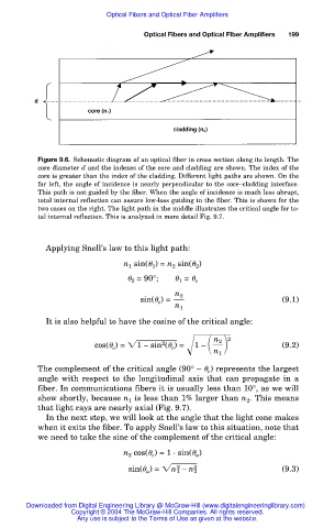
Figure 9.6. Schematic diagram of an optical fiber in cross section along its length. The
core diameter d and the indexes of the core and cladding are shown. The index of the
core is greater than the index of the cladding. Different light paths are shown. On the
far left, the angle of incidence is nearly perpendicular to the core–cladding interface.
This path is not guided by the fiber. When the angle of incidence is much less abrupt,
total internal reflection can assure low-loss guiding in the fiber. This is shown for the
two cases on the right. The light path in the middle illustrates the critical angle for to-
tal internal reflection. This is analyzed in more detail Fig. 9.7.
Applying Snell’s law to this light path:
n 1 sin( 1 ) = n 2 sin( 2 )
2 = 90°; 1 = c
n 2
sin( c ) = (9.1)
n 1
It is also helpful to have the cosine of the critical angle:
2
n 2
2
cos( c ) = 1 – s in ( c ) = 1 – (9.2)
n 1
The complement of the critical angle (90° – c ) represents the largest
angle with respect to the longitudinal axis that can propagate in a
fiber. In communications fibers it is usually less than 10°, as we will
show shortly, because n 1 is less than 1% larger than n 2 . This means
that light rays are nearly axial (Fig. 9.7).
In the next step, we will look at the angle that the light cone makes
when it exits the fiber. To apply Snell’s law to this situation, note that
we need to take the sine of the complement of the critical angle:
n 2 cos( c ) = 1 · sin( a )
sin( a ) = n 1 – n 2 2 (9.3)
2
Downloaded from Digital Engineering Library @ McGraw-Hill (www.digitalengineeringlibrary.com)
Copyright © 2004 The McGraw-Hill Companies. All rights reserved.
Any use is subject to the Terms of Use as given at the website.