
Page 189 - Photoreactive Organic Thin Films
P. 189
MIKHAIL V. KOZLOVSKY, LEV M. BLINOV, AND WOLFGANG HAASE
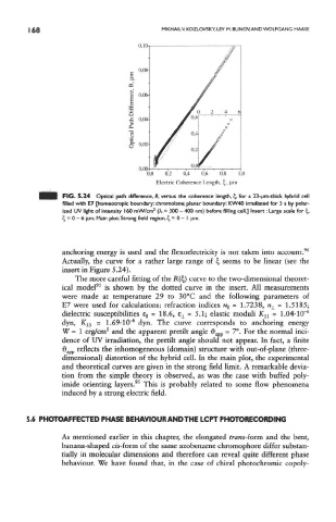
FIG. 5.24 Optical path difference, R, versus the coherence length, %, for a 23-um-thick hybrid cell
filled with E7 [homeotropic boundary: chromolane; planar boundary: KW40 irradiated for 3 s by polar-
2
ized UV light of intensity 160 mW/cm (A, = 300 - 400 nm) before filling cell.] Insert: Large scale for cj,
£, = 0 - 6 |Lim. Main plot: Strong field region, cj = 0 - I jim.
anchoring energy is used and the flexoelectricity is not taken into account. 96
Actually, the curve for a rather large range of £, seems to be linear (see the
insert in Figure 5.24).
The more careful fitting of the H(%) curve to the two-dimensional theoret-
95
ical model is shown by the dotted curve in the insert. All measurements
were made at temperature 29 to 30°C and the following parameters of
E7 were used for calculations: refraction indices % = 1.7238, » ± = 1.5185;
dielectric susceptibilities EH = 18.6, e ± = 5.1; elastic moduli K n = 1.04-10~ 6
6
dyn, K 33 - 1.69' 10" dyn. The curve corresponds to anchoring energy
2
W ~ 1 erg/cm and the apparent pretilt angle d app = 7°. For the normal inci-
dence of UV irradiation, the pretiit angle should not appear. In fact, a finite
d app reflects the inhomogeneous (domain) structure with out-of-plane (three-
dimensional) distortion of the hybrid cell. In the main plot, the experimental
and theoretical curves are given in the strong field limit. A remarkable devia-
tion from the simple theory is observed, as was the case with buffed poly-
95
imide orienting layers. This is probably related to some flow phenomena
induced by a strong electric field.
5.6 PHOTOAFFECTED PHASE BEHAVIOUR AND THE LCPT PHOTORECORDING
As mentioned earlier in this chapter, the elongated trans-form and the bent,
banana-shaped cis-form of the same azobenzene chromophore differ substan-
tially in molecular dimensions and therefore can reveal quite different phase
behaviour. We have found that, in the case of chiral photochromic copoly-