
Page 188 - Photoreactive Organic Thin Films
P. 188
5. CHIRAL POLYMERSWITH PHOTOAFFECTED PHASE BEHAVIOR FOR OPTICAL DATA STORAGE
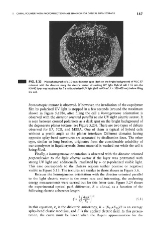
FIG. 5.23 Microphotograph of a 3.3-mm-diameter spot (dark on the bright background) of NLC E7
oriented with the director along the electric vettor of exciting UV light. Hybrid cell, 11.5 ^m. the
2
KW40 layer was irradiated for 7 s with polarized UV light (160 mW/cm , A, = 300-400 nm) before filling
the cell.
homeotropic texture is observed. If however, the irradiation of the copolymer
film by polarized UV light is stopped in a few seconds (around the maximum
shown in Figure 5.10B), after filling the cell a homogeneous orientation is
observed with the director oriented parallel to the UV light electric vector. It
is seen between crossed polarizers as a dark spot on the bright background of
the degenerate planar texture (see Figure 5.23). There are two types of defects
observed for E7, 5CB, and MBBA. One of them is typical of hybrid cells
without a pretilt angle at the planar interface: Different domains having
opposite splay-bend curvatures are separated by disclination lines. The other
type, similar to long brushes, originates from the considerable solubility of
our copolymer in liquid crystals: Some material is washed out while the cell is
being filled.
Finally, a homogeneous orientation is observed with the director oriented
perpendicular to the light electric vector if the layer was pretreated with
strong UV light and additionally irradiated by s- or p-polarized visible light.
This case corresponds to the plateau regions (either positive or negative)
visible in Figure 5.13. The textures are similar to those shown in Figure 5.6.
Because the homogeneous orientation with the director oriented parallel
to the light electric vector is the more rare and interesting, the anchoring
energy measurements were carried out for this latter case. Figure 5.24 shows
the experimental optical path difference, R = <A«>d, as a function of the
following electric coherence length:
In this equation, e a is the dielectric anisotropy, K - (K n+K 33)/2 is an average
splay-bend elastic modulus, and E is the applied electric field. In this presen-
tation, the curve must be linear when the Rapini approximation for the