
Page 303 - Physical Principles of Sedimentary Basin Analysis
P. 303
9.1 Equation for flexure of a plate 285
x
momentum axis
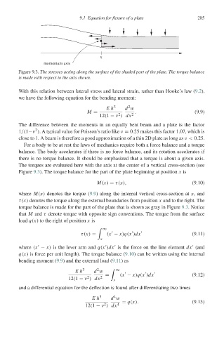
Figure 9.3. The stresses acting along the surface of the shaded part of the plate. The torque balance
is made with respect to the axis shown.
With this relation between lateral stress and lateral strain, rather than Hooke’s law (9.2),
we have the following equation for the bending moment:
2
Eh 3 d w
M = . (9.9)
2
12(1 − ν ) dx 2
The difference between the moments in an equally bent beam and a plate is the factor
2
1/(1−ν ). A typical value for Poisson’s ratio like ν = 0.25 makes this factor 1.07, which is
close to 1. A beam is therefore a good approximation of a thin 2D plate as long as ν< 0.25.
For a body to be at rest the laws of mechanics require both a force balance and a torque
balance. The body accelerates if there is no force balance, and its rotation accelerates if
there is no torque balance. It should be emphasized that a torque is about a given axis.
The torques are evaluated here with the axis at the center of a vertical cross-section (see
Figure 9.3). The torque balance for the part of the plate beginning at position x is
M(x) = τ(x), (9.10)
where M(x) denotes the torque (9.9) along the internal vertical cross-section at x, and
τ(x) denotes the torque along the external boundaries from position x and to the right. The
torque balance is made for the part of the plate that is shown as gray in Figure 9.3. Notice
that M and τ denote torque with opposite sign conventions. The torque from the surface
load q(x) to the right of position x is
∞
τ(x) = (x − x)q(x )dx (9.11)
x
where (x − x) is the lever arm and q(x )dx is the force on the line element dx (and
q(x) is force per unit length). The torque balance (9.10) can be written using the internal
bending moment (9.9) and the external load (9.11)as
2
Eh 3 d w ∞
= (x − x)q(x )dx (9.12)
2
12(1 − ν ) dx 2 x
and a differential equation for the deflection is found after differentiating two times
4
Eh 3 d w
= q(x). (9.13)
2
12(1 − ν ) dx 4