
Page 298 - Physical Principles of Sedimentary Basin Analysis
P. 298
280 Rheology: fracture and flow
5×10 7 7
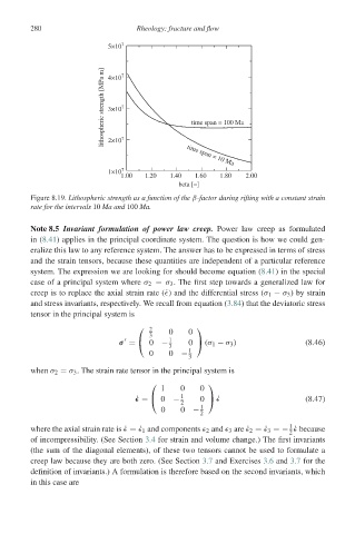
lithospheric strength [MPa m] 4×10 7 7 time span = 100 Ma
3×10
2×10
1×10 7 time span = 10 Ma
1.00 1.20 1.40 1.60 1.80 2.00
beta [−]
Figure 8.19. Lithospheric strength as a function of the β-factor during rifting with a constant strain
rate for the intervals 10 Ma and 100 Ma.
Note 8.5 Invariant formulation of power law creep. Power law creep as formulated
in (8.41) applies in the principal coordinate system. The question is how we could gen-
eralize this law to any reference system. The answer has to be expressed in terms of stress
and the strain tensors, because these quantities are independent of a particular reference
system. The expression we are looking for should become equation (8.41) in the special
case of a principal system where σ 2 = σ 3 . The first step towards a generalized law for
creep is to replace the axial strain rate (˙ ) and the differential stress (σ 1 − σ 3 )bystrain
and stress invariants, respectively. We recall from equation (3.84) that the deviatoric stress
tensor in the principal system is
⎛ 2 ⎞
3 0 0
1
σ = ⎝ 0 − 0 ⎠ (σ 1 − σ 3 ) (8.46)
3
0 0 − 1
3
when σ 2 = σ 3 . The strain rate tensor in the principal system is
⎛ ⎞
1 0 0
˙ = ⎝ 0 − 1 0 ⎠ ˙ (8.47)
2
0 0 − 1
2
1
where the axial strain rate is ˙ =˙ 1 and components 2 and 3 are ˙ 2 =˙ 3 =− ˙ because
2
of incompressibility. (See Section 3.4 for strain and volume change.) The first invariants
(the sum of the diagonal elements), of these two tensors cannot be used to formulate a
creep law because they are both zero. (See Section 3.7 and Exercises 3.6 and 3.7 for the
definition of invariants.) A formulation is therefore based on the second invariants, which
in this case are