
Page 301 - Physical Principles of Sedimentary Basin Analysis
P. 301
9.1 Equation for flexure of a plate 283
F 3
r 1 r 2
O
F 2
F 1
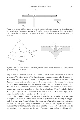
Figure 9.1. A horizontal lever arm is an example of force and torque balance. The forces F i add up
to zero. The sum of the torques M i = r i × F i is also zero, regardless of where the origin is placed.
The torque balance is simplified with respect to the point O, because the torque from the force F 3 is
then zero.
φ
load
R
z w(x) h
σ σ = 0
z = h/2 xx xx
z = 0
(b)
z = −h/2
(a)
Figure 9.2. (a) The lateral stress σ xx in a bent plate (or beam). (b) The deflection w(x) as a function
of distance along a 2D plate.
long as there is a non-zero torque. See Figure 9.1, which shows a lever arm with torques
in balance. The effectiveness of the force increases with the perpendicular distance from
the rotation point to the point of action. The torque is therefore defined as the force times
the perpendicular distance to the force, which in general is the vector product r × F. Since
a deflected plate does not rotate there must be torque balance. The sum of all torques on
the plate must add up to zero. A torque is always defined with respect to an axis, and all
torques must total zero regardless of where the axis is placed. We will begin by finding
the torque along a vertical cross-section of the plate, because it has to match a part of the
torque caused the surface loads (as we will soon see).
Let us for a moment assume that the plate is bent slightly into a circular arc of radius
R. Figure 9.2a shows a vertical cross-section of plate where the bending is exagger-
ated. It is seen from Figure 9.2a that the upper part of the plate undergoes contraction
and that the lower part undergoes extension. The center arc of the plate has its length
unchanged by the bending, and it is therefore called the neutral surface. Let us look at the
arc (or fiber) in the plate that is a distance z from the neutral surface (see Figure 9.2a).