
Page 103 - Pipeline Risk Management Manual Ideas, Techniques, and Resources
P. 103
Scoring the corrosion potential 4/81
tion is employed ideally) every 2 to 15 feet along the entire If survey results are thought to be out of date and provide no
length of the pipeline. In this way, almost all localized inade- useful risk information after, say, 5 years, then the point assign-
quate CP can be detected. It also normally yields some coating ment equation could be:
effectiveness information.
Any aboveground pipeline attachment, including valves, test (maximum points) x (survey age. years)’5
leads, and casing vents, can be used to connect to one side of a
voltmeter. The other side ofthe voltmeter is connected by a wire Using CIS in a more detailed risk assessment model will
to the reference half-cell that is used to make electrical connec- involve an assessment of the type of survey itself, as discussed
tion at the ground surface as the surveyor walks along the in the next paragraphs.
pipeline. The voltmeter and data-logging device are therefore
in the circuit between the two electrodes. Results are usually Scoring of CP effectiveness
interpreted from a chart or database of the measurements that
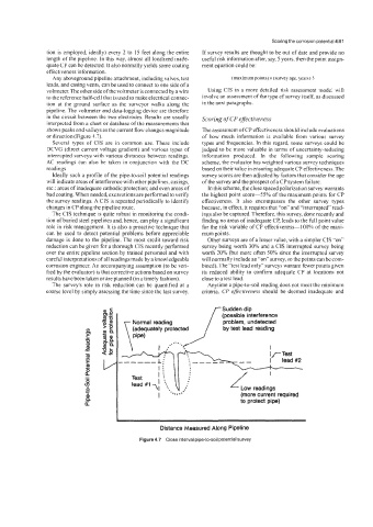
shows peaks and valleys as the current flow changes magnitude The assessment of CP effectiveness should include evaluations
ordirection(Figure 4.7). of how much information is available from various survey
Several types of CIS are in common use. These include types and frequencies. In this regard some surveys could be
DCVG (direct current voltage gradient) and various types of judged to be more valuable in terms of uncertainty-reducing
interrupted surveys with various distances between readings. information produced. In the following sample scoring
AC readings can also be taken in conjunction with the DC scheme, the evaluator has weighted various survey techniques
readings. based on their value in ensuring adequate CP effectiveness. The
Ideally such a profile of the pipe-to-soil potential readings survey scores are then adjusted by factors that consider the age
will indicate areas of interference with other pipelines. casings, of the survey and the prospect of a CP system failure.
etc.; areas of inadequate cathodic protection; and even areas of In this scheme, the close spaced polarization survey warrants
bad coating. When needed, excavations are performed to verify the highest point score-55% of the maximum points for CP
the survey readings. A CIS is repeated periodically to identify effectiveness. It also encompasses the other survey types
changes in CP along the pipeline route. because, in effect, it requires that “on” and “interrupted” read-
The CIS technique is quite robust in monitoring the condi- ings also be captured. Therefore, this survey, done recently and
tion of buried steel pipelines and hence, can play a significant finding no areas of inadequate CP, leads to the full point value
role in risk management. It is also a proactive technique that for the risk variable of CP effectiveness-I 00% of the maxi-
can be used to detect potential problems before appreciable mum points.
damage is done to the pipeline. The most credit toward risk Other surveys are of a lesser value, with a simpler CIS “on”
reduction can be given for a thorough CIS recently performed survey being worth 30% and a CIS interrupted survey being
over the entire pipeline section by trained personnel and with worth 20% (but more often 50% since the interrupted survey
careful interpretations of all readings made by a knowledgeable will normally include an “on” survey, so the points can be com-
corrosion engineer. An accompanying assumption (to be veri- bined). The “test lead only” surveys warrant fewer points given
fied by the evaluator) is that corrective actions based on survey its reduced ability to confirm adequate CP at locations not
results have been taken or are planned (in a timely fashion). close to a test lead.
The survey’s role in risk reduction can be quantified at a Anytime a pipe-to-soil reading does not meet the minimum
coarse level by simply assessing the time since the last survey. criteria, CP effecriveness should be deemed inadequate and
Sudden dip
C Normal reading (possible interference
--- --I- y
problem, undetected
by test lead reading
(adequately protected
..’”‘./
4 u
E I . \ I ---- I
as
I
I I
Test 1
.
lead 7; . .. Low readings
....-
I (more current required
to protect pipe)
Distance Measured Along Pipeline
Figure 4.7 Close interval pipe-to-soil potential survey.