
Page 107 - Pipeline Risk Management Manual Ideas, Techniques, and Resources
P. 107
Scoring the corrosion potential 4185
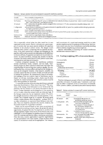
Table 4.6 Sample variables that can be evaluated to assess AC interference potential
lirr.iuhle Nofa laample scoring pmfocols)
Verification Maximum credit given when AC survey is conducted at least annually at distance no greater than I mile: no credit when greater
than 1 mile or more than 2. years between surveys.
.4C present IfAC is detected on the pipeline. penalties assigned where worst case is >I 5 volts (consideration ofpipeline damage only-not
personnel safety issues).
Configuration Assesses the more problematic configurations between the pipeline and the AC power line: parallel and then diverging represents
the highest potential for problems.
Strength Higher strength means higher chance ofproblems.
DlStdnce Shorter distance means greater chance ofproblems: 0.5 mile or greater from current sourceipipeline is best score (unless low-
resistance path exists. such as waterway).
Soil resistivity Lower resistivity means higher chance of probiems.
Mitigation Points are “recovered” based on type of mitigation present.
This is especially critical when the other metal has its own each occurrence of a cased road crossing would be an inde-
impressed current system. Electric railroads are a good exam- pendent pipeline section for purposes of risk scoring. Such sec-
ple of systems that can cause special problems for pipelines tions would carry the risk of interference (including shielding
whether or not physical contact occurs. The danger occurs effects) whereas neighboring sections might not.
when the other system is competing with the pipeline for elec- Specific subvariables in assessing DC-related interference
trons. If the other system has a stronger electronegativity, the include those shown in Table 4.7.
pipeline will become an anode and, depending on the difference
in electron affinity. the pipeline can experience accelerated cor-
rosion. As noted elsewhere, coatings may actually worsen the C3. Coating (weighting: 25% of corrosion threat)
situation if all anodic metal dissolves from pinhole-sized areas,
causing narrow and deep corrosion pits. Corrosion index
Common mitigation measures for interference problems Atmospheric
include interference bonds, isolators. and test leads. Inter- Internal
ference bonds are direct electrical connections that allow the Subsurface
controlled flow of current from one system to another. By con- Subsurface environment
trolling this flow, corrosion effects arising from the foreign sys-
I
tems can be mitigated. Isolators. when properly installed, can I (Coating (25 PW
similarly control the flow of current. Finally, test leads are used Fitness (10PtS)
to monitor for problems. By comparing the pipe-to-soil poten- Condition (15 pts)
tial readings of the two systems, signs of interference can be Cathodic protection (25 pts)
found. As with any monitoring system. checks must be done
regularly by trained personnel, and corrective actions must be Pipeline coatings are one part of the two-part defense against
taken when problems are identified. subsurface corrosion of metallic pipe. Commonly used coat-
A reasonable question when assessing interference potential ings are often a composite of two or more layers of materials.
from other buried metal is “How close is too close?” The prox- Paints, plastics, rubbers, and other hydrocarbon-based products
imity of the foreign metal obviously is a key factor in the risk
potential, but the distance is not strictly measured in feet or
meters. Longer distances can be dangerous in low-resistivity Table 4.7 Sample variables for assessing DC-related interference
soil or in cases where the current levels are relatively high. If
the foreign system also has an impressed current CP system, Relative
the strength and location of the source are also pertinent. A rea- kiable weight Nofes
sonable rule of thumb might be to consider all buried metal
within a certain distance from the pipeline--perhaps 500 ft, if DC present 50?h Investigate for the presence of
potentially interfering currents.
no other calculations or experience-based distances are avail- Configuration 25% Parallel and then divergent might be
able. This rule should be tailored to the specific situation, but worst-case configurations.
then held constant for all pipelines evaluated. Strength 10% This measures CP source strength, if
Points can be assessed based on how many occurrences of any. Intermittent voltages (for
buried metal exist along a section. Again, the greater the area of example, electric trains) are often
opportunity, the greater the risk. For pipelines in corridors with more problematic.
foreign pipelines, higher threat levels of interference may exist Distance 1 0% Use shorter of source distance or
structure (foreign pipeline. rail, etc.).
(although it is not uncommon for pipeline owners in sharedcor- Soil resistivity 5% Lower soil resistivities might lead to
ridors to cooperate and thereby reduce interference potentials). longer distances of interest.
Note that many modem approaches to pipeline segmentation Mitigation Adjustment Improve scores where mitigations are
for risk assessment will create smaller, unique sections where employed.
counts of occurrences would not be appropriate. For instance,