
Page 110 - Pipeline Risk Management Manual Ideas, Techniques, and Resources
P. 110
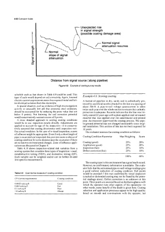
4/88 Corrosion Index

                                                    Unexpected rise
                                                    Unexpected  rise
                                                    in signal strength
                                                    in  signal  strength
                                                    (possible coating damage area)
                                                    (possible  coating  damage  area)
                                     ..
                                     ..                          Normal signal
                                                                 Normal
                                                                        signal
                     5
                     P
                     e
                     c          slope of  signal   *. .' .'
                                slope
                                     of
                                       signal
                     UJ                          *.
                                attenuation
                     m          attenuation
                     c
                     z
                     0
                                                    ~~~           ~~
                                 Distance from signal source (along pipeline)
                                      Figure 4.9  Example of coating survey results.
          schedule such as that shown in Table 4.9 could be used. This   Example 4.6: Scoring coating
          type of scale would depend on soil corrosivity. Again, lowered
          electric current requirements mean less exposed metal and bet-   A buried  oil pipeline in dry, sandy soil is cathodically pro-
          ter electrical isolation from the electrolyte.   tected by sacrificial anodes attached to the line at a spacing of
            A special situation, such as evidence of high microorganism   about  500 ft. A  pipe-to-soil  voltage  measurement  is  taken
          activity or unusually  low pH  that  promotes  steel  oxidation,   twice each year over the whole section to ensure that cathodic
          should be accounted for by reducing the point value (but not   protection is adequate. Records indicate that the line was ini-
          below  0 points).  Not  knowing  the  soil  corrosion  potential   tially coated 22 years ago with a plant-applied coal tar enamel
          would conservatively warrant a score of0 points.   material that  was applied over the sand-blasted  and primed
            A  more  detailed  approach  to  scoring  coating  conditions   pipe. An inspector supervised the coating process. The pipe-
          would be  to use inspection results  directly. Adjustments  are   to-ground potential has not changed measurably  since origi-
          applied to account for age of the inspection-it   is conserva-   nal installation. This section of line has not been exposed for
          tively assumed that coating deteriorates until inspection veri-   10 years.
          fies actual condition. In the case of a visual inspection, a zone   The evaluator assesses the coating condition as follows:
          of influence might be appropriate. Even if only a short length of
          pipe is excavated and inspected, this provides some evidence of   Coating Condition Parameter   Max Weighting   Score
          coating condition for some distance past the excavation if there
          are no known environmental changes. Zone of influence appli-   Coating (good)   25%   20%
          cations are discussed in Chapter 8.        Application (good)         25%      20%
            Table 4.10 shows inspection-related  risk  variables from  a   Inspection (fair)   25%   10%
          scoring system that considers three types of inspection: visual,   Defect correction (fair)   25%   10%
          nondestructive  testing  (NDT), and  destructive testing  (DT).
          Each variable can be weighted andor can be hrther divided             100%     60%
          into specific measurements.
                                                       The coating type in this environment has a good track record.
                                                     However, no confirmatory information is available. The evalu-
                                                     ator feels that the semiannual pipe-to-soil voltage readings give
                                                     a  good indirect  indication  of  coating  condition.  Full  points
          Table 4.9  Quantitative measure of coating condition   would be awarded if this was confirmed by visual inspection
                                                     (cracked or disbonded coating may not be found by the poten-
          CP Current requirements    Coating condition   tial readings alone). Defect correction  is an unknown at this
                                                     point. Three points are awarded based on the thoroughness with
          0.0003 mA/sq ft            Good            which the operator  runs other aspects  of his operations-in
                  ft
          0.003 Msq                  Fair            other words, some benefit of the doubt is given here. Coating
          0.1 MsqA                   Poor
          l.OmA/sqft                 Absent          selection and application processes appear to be high quality,
                                                     based  on  records  and  conversations  with  the  operator,  but