
Page 389 - Pipeline Risk Management Manual Ideas, Techniques, and Resources
P. 389
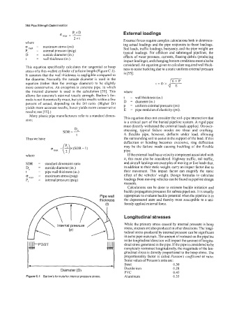
364 Pipe Strength Determination
                                 P,xD                  External loadings
                           Gm,,   =  -
                                 2xt                   External forces require complex calculations both in determin-
            where                                      ing actual loadings and the pipe responses to those loadings.
            0  ma^   =  maximum stress (psi)           Soil loads, traffic loadings, buoyancy, and the pipe weight are
            P,   =  internal pressure (psig)
            D    =  outside diameter (in.)             typical  loadings.  For  offshore  and  submerged pipelines,  the
            t    =  wall thickness (in.).              effects of water pressure, currents, floating debris (producing
                                                       impact loadings), and changing bottom conditions must also be
                                                       considered. An equation given to calculate required wall thick-
            This equation specifically calculates the tangential or hoop   ness to resist buckling due to a static uniform external pressure
            stress of a thin-walled cylinder of infinite length (Figure C.  1).
            It assumes that the wall thickness is negligible  compared to   is [55]:
            the diameter.  Normally the outside diameter is used  in the
            equation  (rather than  the  average  diameter) to be  slightly   t  =  D  X  d  q
            more conservative. An exception is concrete pipe, in which
            the  internal diameter  is  used  in  the  calculation  [55]. This   where
            allows for concrete’s minimal tensile  strength. Barlow’s for-
            mula is not theoretically exact, but yields results within a few   t   =  wall thickness (in.)
            percent  of  actual, depending on  the  Dit  ratio.  (Higher D/t   D   =  diameter(in.)
            yields more accurate results, lower yields more conservative   p   =  uniform external pressure (psi)
                                                          =  pipe modulus of elasticity (psi).
                                                       E
            results; see [55].)
              Many plastic pipe manufacturers refer to a standard dimen-   This equation does not consider the soil-pipe  interaction that
            sion:
                                                       is a critical part of the buried pipeline system. A rigid pipe
                                                       must directly withstand the external loads applied. On over-
                                  DO
                             SDR= -                    stressing,  typical  failure  modes  are  shear  and  crushing.
                                   t                   A  flexible  pipe,  however,  deflects  under  load,  allowing
            Thus we have                               the surrounding soil to assist in the support ofthe load. Ifthis
                                                       deflection  or  bending  becomes  excessive, ring  deflection
                                                       may  be  the  failure mode  causing buckling of the  flexible
                                                       pipe.
            where                                        Ifthe external load has a velocity component associated with
                                                       it, this must also be considered. Highway traffic, rail traffic,
            SDR   =  standard dimension ratio          and aircraft landings are examples of moving or live loads that,
            Do    =  outside diameter (in.)            in addition to their static weight, carry an impact factor due to
            t     =  pipe wall thickness (In.)         their  movement. This  impact  factor  can  magnify  the  static
            IS  maX   =  maximum stress (psig)         effect  of  the vehicles’ weight.  Design  formulas  to calculate
            PI    =  internal pressure (psig)          loadings from moving vehicles can be found in pipeline design
                                                       manuals.
                                                         Calculations can he done to estimate buckle initiation and
                                                       buckle propagation pressures for subsea pipelines. It is usually
                                                        appropriate to evaluate buckle potential when the pipeline is in
                                                       the depressured state and thereby most  susceptible to a uni-
                                                        formly applied external force.

                                                        Longitudinal stresses
                                                        While the primary  stress caused by internal pressure is hoop
                                                        stress, stresses are also produced in other directions. The longi-
                                                        tudinal stress produced by internal pressure can be significant
                                                        in some pipe materiais. The amount of restraint on the pipeline
                                                uu      in the longitudinal direction will impact the amount of longitu-
              /#- PDl2T                                 dinal stress generated in the pipe. If the pipe is considered to be
                                                        completely restrained longitudinally, the magnitude of the lon-
                                                        gitudinal stress is directly proportional to the hoop stress. The
                                                        proportionality  factor is called Poisson k  coefficient or ratio.
                                                        Some values of Poisson’s ratio are:
                                                        Steel                0.30
             1 -                                  -1    Ductile iron         0.28
                            Diameter (D)
                                                        PVC                  0.45
             Figure C.1  Barlow’s formula for internal pressure stress.   Aluminum   0.33