
Page 193 - Pipeline Rules of Thumb Handbook
P. 193
180 Pipeline Rules of Thumb Handbook
P V
.
Where: F F = 096. - 0 28
P C
(Use F L for F LP for line-size valves)
The cavitation index (K c )
The cavitation index (K c ) relates to a condition just prior to
flow choking where cavitation has only partially developed
and flow rate is no longer proportional to the square root of
pressure drop. This condition occurs when:
DP c ≥ K P - P V )
c ( 1
Values for the cavitation index (K c ) can be found in the Valve
Reference Data—Table 2 or 4.
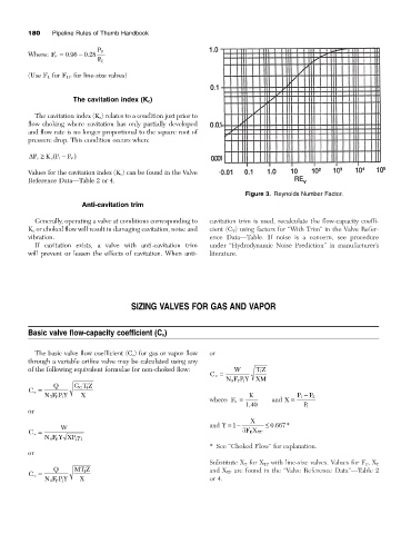
Figure 3. Reynolds Number Factor.
Anti-cavitation trim
Generally, operating a valve at conditions corresponding to cavitation trim is used, recalculate the flow-capacity coeffi-
K c or choked flow will result in damaging cavitation, noise and cient (C V ) using factors for “With Trim” in the Valve Refer-
vibration. ence Data—Table. If noise is a concern, see procedure
If cavitation exists, a valve with anti-cavitation trim under “Hydrodynamic Noise Prediction” in manufacturer’s
will prevent or lessen the effects of cavitation. When anti- literature.
SIZING VALVES FOR GAS AND VAPOR
Basic valve flow-capacity coefficient (C v )
The basic valve flow coefficient (C v ) for gas or vapor flow or
through a variable orifice valve may be calculated using any
of the following equivalent formulae for non-choked flow: W TZ
1
C v =
NF P Y XM
P 1
8
Q GT Z
G
1
C v =
NF P Y X K P - P 2
1
7
P 1
where: F k = and X =
.
140 P 1
or
X
.
W and Y =-1 £ 0 667 *
C v = 3 FX TP
K
NF Y XP 1 1 g
P
6
* See “Choked Flow” for explanation.
or
Substitute X T for X TP with line-size valves. Values for F P , X T
Q MT Z and X TP are found in the “Valve Reference Data”—Table 2
1
C v =
NF P Y X or 4.
P 1
9