
Page 191 - Pipeline Rules of Thumb Handbook
P. 191
178 Pipeline Rules of Thumb Handbook
Limiting Factors for Sonic Velocity (k = 1.4) Excerpted from ( DPP¢ ) = 0 754
.
1
Crane 410Pg A-22 sonic
Since (DP/P¢ 1 ) sonic < (DP/P¢ 1 ) actual , the flow is sonic in the piping.
Thus, we will use Ysonic = 0.680 in the flow calculations
K DP/P¢ 1 Y
(Crane 410 Eq. 3-20).
*
1.2 .552 .588 Since (DP/P¢ 1 ) sonic = .754, then DP = .754 P¢ 1 = 0.754 *
1114.7 = 840.5psi.
1.5 .576 .606 Calculating the system capacity is completed by substitut-
ing the known values into Crane 410 Equation 3-20.
2.0 .612 .622
D PP
*¢ 1
2
¢= 678
Y
3 .622 .639 q m * *d
1
KT S g
4 .697 .649 840 5 *1114 7
.
.
.
¢= 678 *0 680 *(3 068 ) 2
.
q m
.
6 .737 .671 7 33 *960 *1
¢= 50 074
8 .762 .685 q m , SCFM - Air
10 .784 .695 The ASME Pressure Vessel Code, Section VIII, Division 1,
paragraph UG-127(a)(2)(b), also requires that the calculated
15 .818 .702
system capacity using the resistance to flow method must also
be multiplied by a factor of 0.90 to account for uncertainties
20 .839 .710
inherent with this method.
40 .883 .710
*
q ¢ -m ASME = 50 074 0 90 = 45 066 SCFM Air
,
,
.
100 .926 .710
Thus, the system capacity is greater than the required process
capacity (40,000 SCFM Air ).
1114 7 - 14 7
.
.
For this example: DPP¢ ) actual = 1114 7 = 0 9868
(
.
1
.
Reprinted with permission—The Fike Corp. Blue Springs, MO and
From table A-22 at K T = 7.33 Flow Control Magazine
Variable orifice rotary control valves
Flow coefficient (C v ). The flow coefficient, which de-
scribes the flow capacity of a valve, is an empirically deter-
mined constant equal to the valve’s flow capacity in U.S.
gallons per minute of water at 60°F when a pressure drop of
1psi exists across the valve in its most wide-open position.
Table 1 lists C v ’s for all sizes of DANTROL-270 valves, with
and without trim.
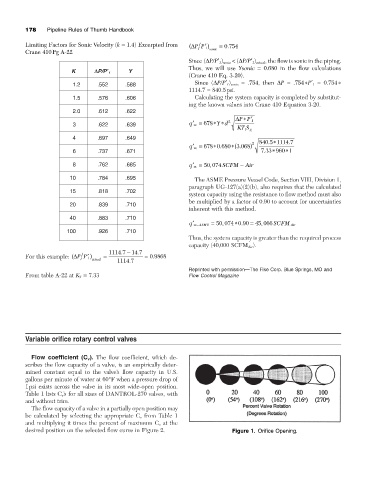
The flow capacity of a valve in a partially open position may
be calculated by selecting the appropriate C v from Table 1
and multiplying it times the percent of maximum C v at the
desired position on the selected flow curve in Figure 2. Figure 1. Orifice Opening.