
Page 187 - Pipeline Rules of Thumb Handbook
P. 187
174 Pipeline Rules of Thumb Handbook
valve, the main valve may only go into partial life since the in every case. If the bellows valve is used for systems with
inlet pipe pressure loss occurs before the pilot has sufficiently superimposed backpressure, the additional built-up back-
vented the dome area for full piston travel. pressure under relieving conditions must be added to arrive
As with direct spring operated valves, capacity is reduced at maximum backpressure.
but under severe inlet pressure loss conditions resonant The performance of pressure relief valves, both as to
chatter may be induced in pilot operated relief valves. This operation and flow capacity, can be achieved through the
chatter is extremely destructive and may result in complete following good discharge piping practices:
valve failure.
On existing installations the corrective action is limited. For • Discharge piping must be at least the same size as the
direct spring operated valves, increasing the blowdown will valve outlet connection and may be increased when nec-
minimize or eliminate rapid cycling if the blowdown can be essary to larger sizes
adjusted to below the initial flowing pressure. • Flow direction changes should be minimized, but when
necessary use long radius elbows and gradual transitions
• If valve has a drain port on outlet side, it should be vented
Resonant chatter to a safe area. Avoid low spots in discharge piping, prefer-
ably pitch piping away from valve outlet to avoid liquid
Resonant chatter occurs with pilot operated relief valves trap at valve outlet
when the inlet piping produces excessive pressure losses at • Proper pipe supports to overcome thermal effects,
the valve inlet. The higher the set pressure or the greater the static loads due to pipe weight and stresses that may
inlet pipe pressure loss, the more likely resonant chatter will be imposed due to reactive thrusts forces must be
occur. considered.
Unlike the rapid cycling noted above, resonant chatter is
uncontrolled; that is, once started, it cannot be stopped unless
the pressure is removed from the valve inlet. In actual appli- Reactive force
cation, however, the valve will self-destruct before a shutdown
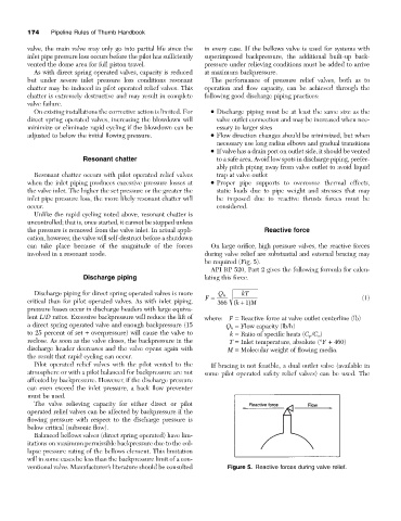
can take place because of the magnitude of the forces On large orifice, high pressure valves, the reactive forces
involved in a resonant mode. during valve relief are substantial and external bracing may
be required (Fig. 5).
API RP 520, Part 2 gives the following formula for calcu-
Discharge piping lating this force.
Discharge piping for direct spring operated valves is more Q h kT
critical than for pilot operated valves. As with inlet piping, F = 366 ( k + ) 1 M (1)
pressure losses occur in discharge headers with large equiva-
lent L/D ratios. Excessive backpressure will reduce the lift of where: F = Reactive force at valve outlet centerline (lb)
a direct spring operated valve and enough backpressure (15 Q h = Flow capacity (lb/h)
to 25 percent of set + overpressure) will cause the valve to k = Ratio of specific heats (C p /C v )
reclose. As soon as the valve closes, the backpressure in the T = Inlet temperature, absolute (°F + 460)
discharge header decreases and the valve opens again with M = Molecular weight of flowing media.
the result that rapid cycling can occur.
Pilot operated relief valves with the pilot vented to the If bracing is not feasible, a dual outlet valve (available in
atmosphere or with a pilot balanced for backpressure are not some pilot operated safety relief valves) can be used. The
affected by backpressure. However, if the discharge pressure
can even exceed the inlet pressure, a back flow preventer
must be used.
The valve relieving capacity for either direct or pilot
operated relief valves can be affected by backpressure if the
flowing pressure with respect to the discharge pressure is
below critical (subsonic flow).
Balanced bellows valves (direct spring operated) have lim-
itations on maximum permissible backpressure due to the col-
lapse pressure rating of the bellows element. This limitation
will in some cases be less than the backpressure limit of a con-
ventional valve. Manufacturer’s literature should be consulted Figure 5. Reactive forces during valve relief.