
Page 183 - Pipeline Rules of Thumb Handbook
P. 183
170 Pipeline Rules of Thumb Handbook
mately 45ft/sec. Experience has shown that the valve veloc-
ity should be limited to about 25ft/sec. The velocity through
the 8-in. valve will be 27ft/sec. The C v for the 8-in. valve with
standard welding reducers is 2,600 and with conical reducers,
the C v is 4,100. The choice of using standard concentric
welding reducers was made because that combination came
closest to satisfying the C v needs. When sizing and selecting
valves, it is important that the valve not be oversized, as this
will always result in poor system control. Reduced-size trim
is available for conventional control valves and ported ball
valves are available.
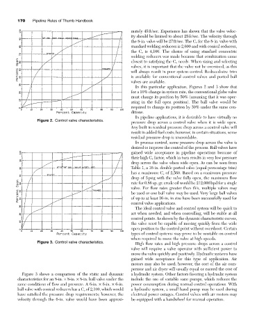
In this particular application, Figures 2 and 3 show that
for a 10% change in system rate, the conventional globe valve
must change its position by 50% (assuming that it was oper-
ating in the full open position). The ball valve would be
required to change its position by 30% under the same con-
ditions.
In pipeline applications, it is desirable to have virtually no
Figure 2. Control valve characteristics.
pressure drop across a control valve when it is wide open.
Any built in residual pressure drop across a control valve will
result in added fuel costs; however, in certain situations, some
residual pressure drop is unavoidable.
In process control, some pressure drop across the valve is
desired to improve the control of the process. Ball valves have
gained wide acceptance in pipeline operations because of
their high C v factor, which in turn results in very low pressure
drop across the valve when wide open. As can be seen from
Table 1, a 16-in. double ported valve (equal percentage trim)
has a maximum C v of 2,560. Based on a maximum pressure
drop of 5psig with the valve fully open, the maximum flow
rate for 0.86 sp. gr. crude oil would be 212,000bpd for a single
valve. For flow rates greater than this, multiple valves may
be used or one ball valve may be used. Very large ball valves
of up to at least 36-in. in size have been successfully used for
control valve applications.
The ideal control valve and control system will be quick to
act when needed, and when controlling, will be stable at all
control points. As shown by the dynamic characteristic curves,
the valve must be capable of moving quickly from the wide
open position to the control point without overshoot. Certain
types of control systems may prove to be unstable on control
when required to move the valve at high speeds.
Figure 3. Control valve characteristics.
High flow rates and high pressure drops across a control
valve will require a valve operator with sufficient power to
move the valve quickly and positively. Hydraulic systems have
gained wide acceptance for this type of application. Air
motors may also be used; however, the cost of the air com-
pressor and air dryer will usually equal or exceed the cost of
Figure 3 shows a comparison of the static and dynamic a hydraulic system. Other factors favoring a hydraulic system
characteristics for an 8-in. ¥ 8-in. ¥ 8-in. ball valve under the include the use of variable vane pumps, which reduces the
same conditions of flow and pressure. A 6-in. ¥ 6-in. ¥ 6-in. power consumption during normal control operations. With
ball valve with conical reducers has a C v of 2,100, which would a hydraulic system, a small hand pump may be used during
have satisfied the pressure drop requirements; however, the electrical power outages. Control valves with air motors may
velocity through the 6-in. valve would have been approxi- be equipped with a handwheel for manual operation.