
Page 182 - Pipeline Rules of Thumb Handbook
P. 182
Control Valves 169
Control valve selection
A control valve may be thought of as a section of pipe with Table 1
a variable resistance. Control valves are typically used to Typical Values of C v for Control Valves*
match pumps to the pipeline system characteristics. They are (Equal Percentage Trim)
not normally used with reciprocating compressors but may be
Double Single
used with centrifugal compressors for preventing surge.
Valve Ported Ported Ball Valve
Liquid pipeline applications usually involve controlling the †
Size Globe Globe Full Bore
flow rate, suction and discharge pressure, and other variables
for centrifugal pumps. Control valves may also be used with 2 48 46 406
reciprocating pumps to regulate the pump discharge pressure 4 195 195 1,890
by recycling fluid from the pump discharge to the pump 6 450 400 4,580
suction when the discharge pressure approaches the control 8 750 640 8,900
point. The control valve may also be used to unload the pump 10 1,160 1,000 14,600
during the start-up by opening just prior to start-up and slowly 12 1,620 22,800
closing after the pump driver is up to operating speed. 14 2,000 28,700
16 2,560 38,900
Other applications for control valves include:
20 66,000
24 98,600
• Pressure reduction 26 119,800
• Pressure relief
• Back pressure control * These values are suitable for estimating only. The valve manufacturer
• Control delivery flow rates should be consulted for the actual C v for the valve selected.
† Courtesy: Thunderco—Houston.
Ideally, the pump(s) for a system will be sized such that a
minimum amount of pressure throttling will be required
during normal operations. System startup, system upsets, and
unit startup and shutdown require that a means be provided
to regulate pressures, flow rates, and in some cases motor
load. This may be accomplished by using variable speed
motors, variable speed couplings, or a control valve.
The control valve, when used with centrifugal pumping
units, is installed in the pump discharge line. If multiple
pumping units are used, only one control valve will be
required.
Table 1 lists typical values of C v for conventional and ball
control valves.
When conventional globe-type control valves are used in
pipeline applications for pump control, valves with equal per-
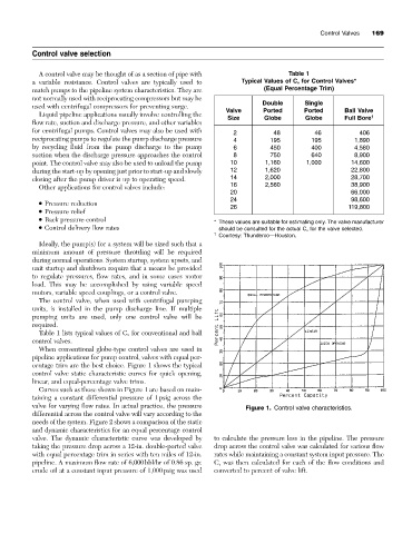
centage trim are the best choice. Figure 1 shows the typical
control valve static characteristic curves for quick opening,
linear, and equal-percentage valve trims.
Curves such as those shown in Figure 1 are based on main-
taining a constant differential pressure of 1psig across the
valve for varying flow rates. In actual practice, the pressure Figure 1. Control valve characteristics.
differential across the control valve will vary according to the
needs of the system. Figure 2 shows a comparison of the static
and dynamic characteristics for an equal percentage control
valve. The dynamic characteristic curve was developed by to calculate the pressure loss in the pipeline. The pressure
taking the pressure drop across a 12-in. double-ported valve drop across the control valve was calculated for various flow
with equal percentage trim in series with ten miles of 12-in. rates while maintaining a constant system input pressure. The
pipeline. A maximum flow rate of 6,000bbl/hr of 0.86 sp. gr. C v was then calculated for each of the flow conditions and
crude oil at a constant input pressure of 1,000psig was used converted to percent of valve lift.