
Page 180 - Pipeline Rules of Thumb Handbook
P. 180
Control Valves 167
Table 1 verted to a K factor by using Figure 2. In this case, 6-in. K v
is 0.05.
Pipe resistance must also be considered (Figure 5). The
L/D ratio must be calculated with reference to the same units
of L and D. In the example, 12ft of 6-in. pipe has a K p equal
to 0.36.
All resistances must be converted to the same base diam-
eter (in this case 6in.). The entrance factor, K e is 0.05 for 12-
in. Referring to Figure 6, the 6-in. K e is about 0.04; the 12-in.
elbow coefficient converted to 6-in., 6-in. K el is 0.02, and the
12-in. exit coefficient, 6-in. K x , is 0.8. A tabulation and sum of
these coefficients as determined from Figure 3 would be:
All K factors, L/D’s or C v ’s must be converted to the same 12≤ Entrance 6≤ K e = 0.04
basis using the same diameter d when using an over-all C v for 6≤ Reducer—Increaser 6≤ K ri = 0.80
a piping run. This can be accomplished with the following 2–6≤ Valves 6≤ K v = 0.10
equations: 6≤ Control Valve 6≤ K v = 10.00
12-ft spool of 6≤ Pipe 6≤ K p = 0.36
4
b (
K a = K f f b )( d d b ) (8) 12≤ Elbow 6≤ K el = 0.02
a
a
12≤ Exit 6≤ K x = 0.08
4
( LD) = ( LD) ( d d b ) (9) SK = 11.40
a b a
( ) = ( ) ( d d a ) 2 (10) Refer to Figure 2 for a conversion of K to C v . With the
b
C v a
C v b
above values noted, the overall 6-in. C v is 320, approximately
a 6% reduction of the original C v of 340.
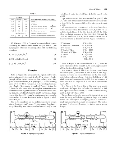
Examples Now refer to Figure 4. This is an identical control valve
run with Figure 3, except that a 6-in. ¥ 4-in. ¥ 6-in. high-
Refer to Figure 3 for a schematic of a typical control valve capacity ball valve has been substituted for the 6-in. single-
station using an old style control valve. Flow is from a header ported globe body control valve. Note that the SK now is 1.93,
through a 12-in. by 6-in. reducer, a 6-in. isolating valve, 6-in. which converted to an overall C v is 775. This is a reduction of
globe body control valve, 6-in. pipe spool, a second isolating about 48% from the original 6-in. ¥ 4-in. ¥ 6-in. control valve
valve, a 6-in. by 12-in. increaser, a 12-in. welding elbow and C v of 1,495.
into a header. Note should be made of Figure 1 in that the If in Figure 4, the 6-in. ¥ 4-in. ¥ 6-in. valve were substi-
C v from the solid curve is for the complete reducer-increaser tuted with a full open 6-in. ball valve, the overall C v is 895.
combination with regard to the ratio of diameters. In this case, This represents a reduction in C v of about 81% from the orig-
the Beta ratio is 6/12 or 0.5 and C v is 1,200 for the small diam- inal 6-in. ball valve C v of 4,700.
eter of 6-in. Since C v ’s cannot be simply added, they must be The methods and graphs presented in this article are pro-
converted to K factors. To do this, refer to Figure 2, which posed for sizing and calculating pressure drops in a control
converts C v to K. station. The assumption of assigning values to certain un-
Also to be considered are the isolating valves and control usual piping configuration must be recognized. The author
valves. Resistance coefficients, C v ’s or pressure drop factors has some field data confirmation on similar control station
are published by most valve manufacturers and may be con- designs.
Figure 3. Piping configuration. Figure 4. Piping configuration.