
Page 176 - Pipeline Rules of Thumb Handbook
P. 176
Control Valves 163
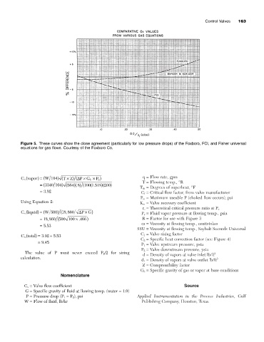
Figure 5. These curves show the close agreement (particularly for low pressure drops) of the Foxboro, FCI, and Fisher universal
equations for gas flows. Courtesy of the Foxboro Co.
C vapor) = ( W 104 ) ( T ¥ Z) (D P G b ¥ ) q = Flow rate, gpm
v (
¥
P 2
T = Flowing temp., °R
= (3340 104 ) (564 8. (1 518. )(200 )
)( ) (100
T sh = Degrees of superheat, °F
= 392 C f = Critical flow factor, from valve manufacturer
.
P m = Maximum useable P (choked flow occurs), psi
Using Equation 2: K m = Valve recovery coefficient
r c = Theoretical critical pressure ratio at P v
v (
C liquid) = ( W 500 ) (18 860, D P G) P v = Fluid vapor pressure at flowing temp., psia
¥
.
,
= 18 860 (500 100 ¥ 466 ) R = Factor for use with Figure 3
cs = Viscosity at flowing temp., centistokes
= 553
.
SSU = Viscosity at flowing temp., Saybolt Seconds Universal
v (
C total) = 392 + 5 53 C 1 = Valve sizing factor
.
.
C 2 = Specific heat correction factor (see Figure 4)
= 945
.
P 1 = Valve upstream pressure, psia
P 2 = Valve downstream pressure, psia
The value of P must never exceed P 2 /2 for sizing 3
d = Density of vapors at valve inlet lb/ft
calculation. 3
d 1 = Density of vapors at valve outlet lb/ft
Z = Compressibility factor
G b = Specific gravity of gas or vapor at base conditions
Nomenclature
C v = Valve flow coefficient Source
G = Specific gravity of fluid at flowing temp. (water = 1.0)
P = Pressure drop (P 1 - P 2 ), psi Applied Instrumentation in the Process Industries, Gulf
W = Flow of fluid, lb/hr Publishing Company, Houston, Texas.