
Page 173 - Pipeline Rules of Thumb Handbook
P. 173
160 Pipeline Rules of Thumb Handbook
Control valve sizing formulas
Liquid formulas (noncompressible fluids).
Volume basis:
D
C v = q G P (1)
Weight basis:
C v = W (500 D P G) (2)
¥
Equations 1 and 2 exclude control valve calculations where
flashing, high viscosity, two-phase flow or high pressure drops
are involved.
Gas and vapors (other than steam).
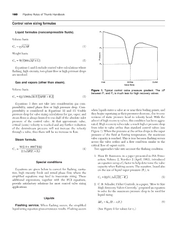
Volume basis: Figure 1. Typical control valve pressure gradient. The DP
between P 1 and P 2 is much less for high recovery valves.
C v = ( Q 1360 2 GT [D P P + )] (3)
)
P 2
( 1
Equations 3 does not take into consideration gas com-
pressibility, mixed phase flow or high pressure drop. Com-
pressibility is considered in Equations 12 and 13. Usable when liquids enter a valve at or near their boiling points, and
pressure drop for valve sizing calculations for gas, vapor, and they begin vaporizing as their pressures decrease, due to con-
steam flows is always limited to one-half of the absolute inlet versions of static pressure head to velocity head. With the
pressure of the control valve. At that approximate value, advent of high recovery valves, this condition has been aggra-
critical (sonic) velocity is reached and any further reduction vated. High recovery valves take a much higher pressure drop
of the downstream pressure will not increase the velocity from inlet to valve orifice than standard control valves (see
through a valve, thus there will be no increase in flow. Figure 1). When the pressure at the orifice drops to the vapor
pressure of the fluid at flowing temperature, the maximum
valve capacity is reached. This is true because flashing occurs
Steam formula.
across the valve orifice and a flow condition similar to the
critical flow of vapors exists.
.
.
W(1 0 + 0007 Tsh)
C v = (4) Two approaches take into account the flashing condition:
.
21 D PP + )
P 2
( 1
1. Hans D. Baumann, in a paper presented in ISA Trans-
action, Volume 2, Number 2 (April, 1963), introduced
Special conditions an equation using a C f factor to help determine the valve
capacity when flashing occurs. The equation, based also
Equations are given below to correct for flashing, cavita- on the use of liquid vapor pressure (P v ), is
tion, high viscosity fluids and mixed phase flow, where the
simplified equations may lead to inaccurate sizing. These C v = ( Q C f ) GP - ) (5)
( 1
P v
additional expressions, together with the FCI equations,
provide satisfactory solutions for most control valve sizing 2. C. B. Schuder, Fisher Controls, in a paper, “How to Size
applications. High Recovery Valves Correctly,” proposed an equation
to solve for the maximum pressure drop to be used for
liquid sizing:
Liquids
DP m = K P - r P v ) (6)
c
m ( 1
Flashing service. When flashing occurs, the simplified
liquid sizing equation gives erroneous results. Flashing occurs (See Figure 2 for values for r c .)