
Page 170 - Pipeline Rules of Thumb Handbook
P. 170
Pipeline Drying 157
Phase 3—Final drying What is dryness?
Once the free water has been converted into water vapour, The dryness of a pipeline is measured in terms of dewpoint,
the majority of it must be removed from the pipeline in order which is the temperature at which mist or dew will begin to
to reach the required dryness level. This is achieved by reduc- form. A convenient method of measuring dewpoint is to use
ing the pressure in the pipeline still further which has the an instrument called a mirror hygrometer where the water
effect of drawing the water vapour out of the pipeline through vapour is passed across a polished surface which is slowly
the vacuum equipment. Obviously, the more water vapour cooled until dew forms. The temperature at which the dew
removed, then the drier the pipeline will become. forms is the dewpoint of the water vapour and is normally
During this phase a careful watch is kept on the slope expressed in degrees centigrade. The drier the air, the lower
of the final drying line to ensure that it follows the calcu- the temperature at which dew will form.
lated value, since a shallower slope would indicate the con- In terms of a pipeline being vacuum dried, the lower the
tinuing presence of some free water still remaining in the pressure in the pipeline, the lower the dewpoint will be. For
pipeline. example, at a pressure level of 0.26kPaA, the equivalent dew-
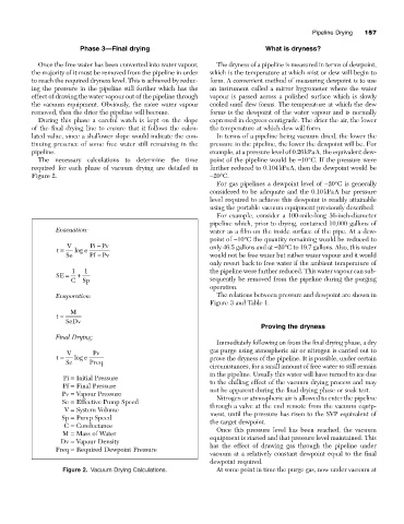
The necessary calculations to determine the time point of the pipeline would be -10°C. If the pressure were
required for each phase of vacuum drying are detailed in further reduced to 0.104kPaA, then the dewpoint would be
Figure 2. -20°C.
For gas pipelines a dewpoint level of -20°C is generally
considered to be adequate and the 0.10kPaA bar pressure
level required to achieve this dewpoint is readily attainable
using the portable vacuum equipment previously described.
For example, consider a 100-mile-long 36-inch-diameter
pipeline which, prior to drying, contained 10,000 gallons of
Evacuation: water as a film on the inside surface of the pipe. At a dew-
point of -10°C the quantity remaining would be reduced to
-
V Pi Pv only 46.5 gallons and at -20°C to 19.7 gallons. Also, this water
t = log e
Se Pf - Pv would not be free water but rather water vapour and it would
only revert back to free water if the ambient temperature of
1 1 the pipeline were further reduced. This water vapour can sub-
SE = +
C Sp sequently be removed from the pipeline during the purging
operation.
Evaporation: The relations between pressure and dewpoint are shown in
Figure 3 and Table 1.
M
t =
SeDv
Proving the dryness
Final Drying:
Immediately following on from the final drying phase, a dry
V Pv gas purge using atmospheric air or nitrogen is carried out to
t = log e prove the dryness of the pipeline. It is possible, under certain
Se Pr eq
circumstances, for a small amount of free water to still remain
in the pipeline. Usually this water will have turned to ice due
Pi = Initial Pressure
Pf = Final Pressure to the chilling effect of the vacuum drying process and may
Pv = Vapour Pressure not be apparent during the final drying phase or soak test.
Nitrogen or atmospheric air is allowed to enter the pipeline
Se = Effective Pump Speed through a valve at the end remote from the vacuum equip-
V = System Volume
Sp = Pump Speed ment, until the pressure has risen to the SVP equivalent of
the target dewpoint.
C = Conductance
M = Mass of Water Once this pressure level has been reached, the vacuum
Dv = Vapour Density equipment is started and that pressure level maintained. This
Preq = Required Dewpoint Pressure has the effect of drawing gas through the pipeline under
vacuum at a relatively constant dewpoint equal to the final
dewpoint required.
Figure 2. Vacuum Drying Calculations. At some point in time the purge gas, now under vacuum at