
Page 174 - Pipeline Rules of Thumb Handbook
P. 174
Control Valves 161
R = (10 000 ¥ q) C v ¥ cs (7)
,
This equation is used for viscosity values between 100 and
200 SSU; the viscosity must be converted to centistokes.
When viscosities exceed 200 SSU, Equation 8 applies:
R = (46 500 ¥ q) C v ¥ SSU (8)
,
In either equation, the following steps should be followed:
1. Solve for C v , assuming no viscosity effects.
2. Solve for factor R using Equation 7 or 8.
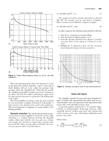
3. From the viscosity correction curve, Figure 3, read the
correction factor at the intercept of factor R on the
curve.
4. Multiply the C v obtained in Step 1 by the correction
factor obtained in Step 3 for the corrected C v .
Figure 2. These critical pressure ratios (r c ) are for use with
Equation 6.
When this limiting pressure drop from Equation 6 is used
in the liquid flow formula, Equation 1 gives a valve size in
Figure 3. Viscosity correction curve for use with Equation 8.
which flashing will not occur, unless the pressure drop
increases above the calculated DP m . When the DP exceeds
DP m , flashing and possible cavitation can occur. Cavitation is
the effect caused by the sudden condensing of vapors when Gases and vapors
the static pressure increases to a point above the boiling point
of the liquid. The simplified equation for gases and vapors (Equation 3)
When the possibility of cavitation exists, the process should agrees favorably with experimental data when used for con-
be reviewed and the condition eliminated if at all possible. A ventional globe valves, but agreement with experimental data
high recovery valve should not be used in this application. is poor when used with high recovery valves.
This second approach is suggested as a good solution to the A universal equation proposed by C. B. Schuder, Fisher
flashing problem. Controls, in Instrumentation Technology, February, 1968,
reportedly showed excellent agreement with experimental
Viscosity correction. The liquid sizing formulas in gen- results covering a wide range of body plug configurations and
eral use have no factor applied to correct for viscosity. This pressure drop ratios.
correction is a complex function involving the Reynolds
number which varies with the valve size, port area, velocity, Volume basis:
and viscosity. No correction is required for a viscosity value
below 100 SSU. Above viscosity values of 100 SSU, two equa- 520 È 3417 D P ˘
Q = CC C P 1 sin Í ˙ Deg. (9)
v
2
1
tions are given to obtain correction factors: GT Î CC 2 P ˚
1
1