
Page 175 - Pipeline Rules of Thumb Handbook
P. 175
162 Pipeline Rules of Thumb Handbook
Weight basis: To correct for deviation from the universal gas law, the
compressibility factor is inserted in Equation 11, becoming:
È 3417 D P ˘
.
W = 106 dP ZC C C v1 1 2 sin Í ˙ Deg. (10) C v = ( ) P P )
Î CC 2 P ˚ Q 1360 G TZ (D ¥ 2 (12)
b
1
1
The C 1 factor in Equations 9 and 10 is currently available On a weight basis, this equation becomes:
from Fisher Controls for their valves. Other companies pre-
¥
sumably do not publish this factor. (The C 2 factor is shown in C v = ( W 104 ) TZ (D P P ¥ G b ) (13)
2
Figure 4.)
Mixed phase flow. Mixed phase flow is generally experi-
enced when:
1. Liquid entrainment is carried by a gaseous flow.
2. Liquid at or near its boiling point vaporizes as it flows
through a line and its restrictions.
In the discussion under “Flashing Service,” it is explained
that flashing can be reduced or eliminated by limiting the DP
across the valve. When two-phase flow already exists or when
it occurs in the control valve, two methods are given to size
the valve.
1. A rule of thumb that has been used for years is to cal-
culate the C v based on liquid only and increase the valve
body to the next size. This is satisfactory in many cases,
but it obviously does not take into account varying ratios
of liquid to vapor.
2. A preferred method is to determine the amount of vapor
and liquid, then calculate and add the C v of each phase
to get the overall C v requirement. The percent vapor-
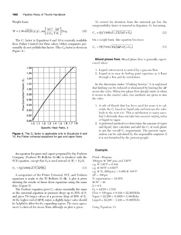
Figure 4. The C 2 factor is applicable only to Equations 9 and ization can be calculated by the responsible engineer if
10, the Fisher universal equations for gas and vapor flows.
it is not furnished by the process people.
Example.
An equation for gases and vapors proposed by the Foxboro
Company (Foxboro TI Bulletin 31-4K) is identical with the Fluid—Propane
FCI equation, except that P 2 is used instead of (P 1 + P 2)/2: 100gpm @ 300°psia and 130°F
s.g. @ 130°F = 0.444
C v = ( Q 1360 ) GT D P P () (11) s.g. @ 60°F = 0.5077
2
s.g. @ P 2 (200psia) = 0.466 @ 104°F
A comparison of the Fisher Universal, FCI, and Foxboro DP = 100psi
equations is made in the TI Bulletin 31-4K. A plot is given % vaporization = 15.05%
showing the results of these three equations using the same M.W. = 44
data (Figure 5). Z = 0.8
The Foxboro equation gives C v values essentially the same G b = 44/29 = 1.518
Flow = 100gpm ¥ 0.444 = 22,200lb/hr
as the universal equation at pressure drops up to 25% of P 1
and gives 7% larger values at a pressure drop of 50% of P 1. Vapor = 22,200 ¥ 0.1505 = 3,340lb/hr
At the higher end of DP/P 1 ratios, a slightly larger valve should Liquid = 22,200 - 3,340 = 18,860lb/hr
be helpful to allow for the expanding vapors. The same agree-
ment is claimed for steam flows although no plot is given. Using Equation 13: