
Page 184 - Pipeline Rules of Thumb Handbook
P. 184
Control Valves 171
RELIEF VALVE SIZING, SELECTION,
INSTALLATION AND TESTING
Effectiveness of a Safety Relief Valve Depends on Proper Sizing and Type of Equipment Selected
Gary B. Emerson, Manager SVR Products, Anderson-Greenwood USA, Bellaire, Texas
A safety relief valve is an essential and important piece of Sonic flow
equipment on virtually any pressured system. Required by
the ASME-UPV Code, among others, it must be carefully In accordance with API RP 520, Part 1, Section 3.3, the
sized to pass the maximum flow produced by emergency formulas used for calculating orifice areas for sonic flow are:
conditions.
After it is installed, the user hopes that it will never have WTZ
to operate, which makes the safety relief valve rather unique A = CKP M
as compared to other types of process equipment. 1
QZ
or A =
Sizing 18 3 Ê C ˆ 520 29
.
KP 1
Ë 356 ¯ T M
The sizing formulas for vapors and gases fall into two
2
general categories, based on the flowing pressure with respect where: A = Calculated orifice area (in. )
to the discharge pressure. When the ratio of P 1 (set pressure W = Flow capacity (lb/h)
plus allowable accumulation) to P 2 (outlet pressure) is greater Q = Flow capacity (scfm)
than two, the flow through the relief valve is sonic; the flow M = Molecular weight of flowing media
reaches the speed of sound for the particular flowing medium. T = Inlet temperature, absolute (°F + 460)
Once the flow becomes sonic, the velocity remains constant; Z = Compressibility factor
it cannot go supersonic. No decrease of P 2 will increase the C = Gas constant based on ratio of specific heats
flowrate. (Table 1)
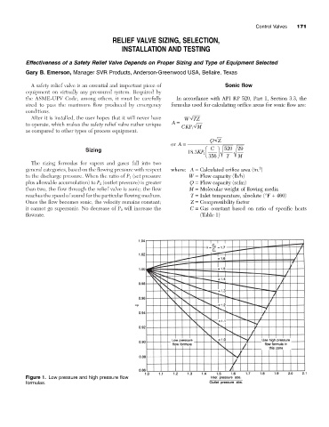
Figure 1. Low pressure and high pressure flow
formulas.