
Page 185 - Pipeline Rules of Thumb Handbook
P. 185
172 Pipeline Rules of Thumb Handbook
K = Valve coefficient of discharge Table 1
P 1 = Inlet pressure, psia (set pressure + accumulation Gas Constant Based on Ratio of Heats
+ atmos. pres.)
Gas Mol. Wt. C p /C v C
Acetylene 26 1.26 343
Subsonic flow
Air 29 1.40 356
Ammonia 17 1.31 348
The second general category for vapor or gas sizing is gen-
Argon 40 1.67 378
erally when P 2 is greater than half of P 1 (backpressure greater Benzene 78 1.12 329
than half of inlet pressure). Butadiene 54 1.12 324
Using k (ratio of specific heats) and P 1 /P 2 (absolute), Carbon dioxide 44 1.28 345
confirm from Fig. 1 that the subsonic (“low pressure”) flow Carbon monoxide 28 1.40 356
formula is required. If so, then determine “F” factor. If not, Ethane 30 1.19 336
use above sonic flow formula. Ethylene 28 1.24 341
Freon 22 86.47 1.18 335
QGI Helium 4 1.66 377
A = Hexane 86 1.06 322
863 KF ( 1 P 2 P 2 Hydrogen 2 1.41 357
P - ) ¥
Hydrogen sulfide 34 1.32 349
where: G = Specific gravity Methane 16 1.31 348
F = Factor obtained from Table 1 Methyl mercapton 48.11 1.20 337
P 2 = Outlet pressure, psia (backpressure + atmos. N-Butane 58 1.09 326
pres.) Natural gas (0.60) 17.4 1.27 344
Nitrogen 28 1.40 356
After determining the calculated orifice area, select the Oxygen 32 1.40 356
next largest standard orifice size from the relief valve manu- Pentane 72 1.07 323
Propane 44 1.13 330
facturer’s catalog.
Propylene 42 1.15 332
Sulfur dioxide 64 1.29 346
VCM 62.5 1.18 335
Selection
The fundamental selection involves the consideration of
the two basic types of relief valves more commonly used; con-
ventional spring-loaded type and pilot operated relief valves.
Advantages of the spring-loaded relief valves are:
• Competitive price at lower pressures and in smaller sizes
• Wide range of chemical compatibility
• Wide range of temperature compatibility, particularly at
higher temperatures.
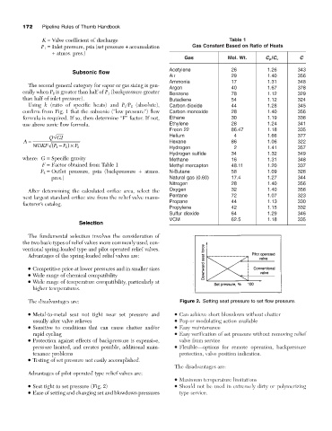
The disadvantages are: Figure 2. Setting seat pressure to set flow pressure.
• Metal-to-metal seat not tight near set pressure and • Can achieve short blowdown without chatter
usually after valve relieves • Pop or modulating action available
• Sensitive to conditions that can cause chatter and/or • Easy maintenance
rapid cycling • Easy verification of set pressure without removing relief
• Protection against effects of backpressure is expensive, valve from service
pressure limited, and creates possible, additional main- • Flexible—options for remote operation, backpressure
tenance problems protection, valve position indication.
• Testing of set pressure not easily accomplished.
The disadvantages are:
Advantages of pilot operated type relief valves are:
• Maximum temperature limitations
• Seat tight to set pressure (Fig. 2) • Should not be used in extremely dirty or polymerizing
• Ease of setting and changing set and blowdown pressures type service.