
Page 186 - Pipeline Rules of Thumb Handbook
P. 186
Control Valves 173
Installation procedures
Safety relief valve installation requires that careful con-
sideration be given to inlet piping, discharge piping, pressure
sense lines (where used) and bracing if required. Any mar-
ginal installation practice can render the safety relief valve
inoperable, at worst, or severely restrict its design capacity
at best. Either condition compromises the safety of the
installation.
Inlet piping
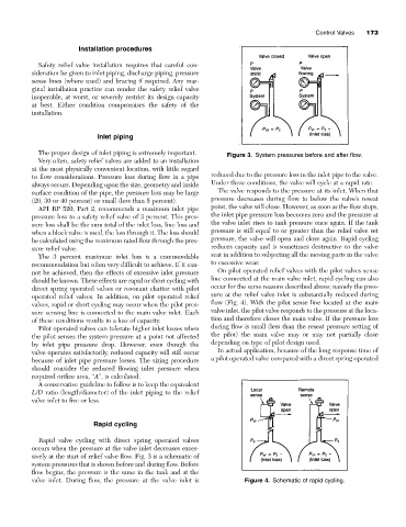
The proper design of inlet piping is extremely important. Figure 3. System pressures before and after flow.
Very often, safety relief valves are added to an installation
at the most physically convenient location, with little regard
to flow considerations. Pressure loss during flow in a pipe reduced due to the pressure loss in the inlet pipe to the valve.
always occurs. Depending upon the size, geometry and inside Under these conditions, the valve will cycle at a rapid rate.
surface condition of the pipe, the pressure loss may be large The valve responds to the pressure at its inlet. When that
(20, 30 or 40 percent) or small (less than 5 percent). pressure decreases during flow to below the valve’s reseat
API RP 520, Part 2, recommends a maximum inlet pipe point, the valve will close. However, as soon as the flow stops,
pressure loss to a safety relief valve of 3 percent. This pres- the inlet pipe pressure loss becomes zero and the pressure at
sure loss shall be the sum total of the inlet loss, line loss and the valve inlet rises to tank pressure once again. If the tank
when a block valve is used, the loss through it. The loss should pressure is still equal to or greater than the relief valve set
be calculated using the maximum rated flow through the pres- pressure, the valve will open and close again. Rapid cycling
sure relief valve. reduces capacity and is sometimes destructive to the valve
The 3 percent maximum inlet loss is a commendable seat in addition to subjecting all the moving parts in the valve
recommendation but often very difficult to achieve. If it can- to excessive wear.
not be achieved, then the effects of excessive inlet pressure On pilot operated relief valves with the pilot valves sense
should be known. These effects are rapid or short cycling with line connected at the main valve inlet, rapid cycling can also
direct spring operated valves or resonant chatter with pilot occur for the same reasons described above; namely the pres-
operated relief valves. In addition, on pilot operated relief sure at the relief valve inlet is substantially reduced during
valves, rapid or short cycling may occur when the pilot pres- flow (Fig. 4). With the pilot sense line located at the main
sure sensing line is connected to the main valve inlet. Each valve inlet, the pilot valve responds to the pressure at the loca-
of these conditions results in a loss of capacity. tion and therefore closes the main valve. If the pressure loss
Pilot operated valves can tolerate higher inlet losses when during flow is small (less than the reseat pressure setting of
the pilot senses the system pressure at a point not affected the pilot) the main valve may or may not partially close
by inlet pipe pressure drop. However, even though the depending on type of pilot design used.
valve operates satisfactorily, reduced capacity will still occur In actual application, because of the long response time of
because of inlet pipe pressure losses. The sizing procedure a pilot operated valve compared with a direct spring operated
should consider the reduced flowing inlet pressure when
required orifice area, “A”, is calculated.
A conservative guideline to follow is to keep the equivalent
L/D ratio (length/diameter) of the inlet piping to the relief
valve inlet to five or less.
Rapid cycling
Rapid valve cycling with direct spring operated valves
occurs when the pressure at the valve inlet decreases exces-
sively at the start of relief valve flow. Fig. 3 is a schematic of
system pressures that is shown before and during flow. Before
flow begins, the pressure is the same in the tank and at the
valve inlet. During flow, the pressure at the valve inlet is Figure 4. Schematic of rapid cycling.