
Page 190 - Pipeline Rules of Thumb Handbook
P. 190
Control Valves 177
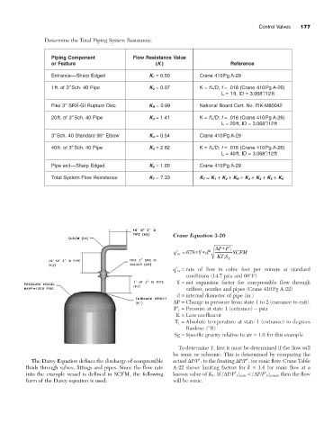
Determine the Total Piping System Resistance:
Piping Component Flow Resistance Value
or Feature (K ) Reference
Entrance—Sharp Edged K 1 = 0.50 Crane 410Pg A-29
1ft. of 3≤Sch. 40 Pipe K 2 = 0.07 K = fL/D; f = .018 (Crane 410Pg A-26)
L = 1ft, ID = 3.068≤/12ft
Fike 3≤ SRX-GI Rupture Disc K R = 0.99 National Board Cert. No. FIK-M80042
20ft. of 3≤Sch. 40 Pipe K 3 = 1.41 K = fL/D; f = .018 (Crane 410Pg A-26)
L = 20ft, ID = 3.068≤/12ft
3≤Sch. 40 Standard 90° Elbow K 4 = 0.54 Crane 410Pg A-29
40ft. of 3≤Sch. 40 Pipe K 5 = 2.82 K = fL/D; f = .018 (Crane 410Pg A-26)
L = 40ft, ID = 3.068≤/12ft
Pipe exit—Sharp Edged K 6 = 1.00 Crane 410Pg A-29
Total System Flow Resistance K T = 7.33 K T = K 1 + K 2 + K R + K 3 + K 4 + K 5 + K 6
Crane Equation 3-20
D PP
*¢ 1
¢= 678 * *d 2 SCFM
Y
q m
KT S g
1
q¢ m = rate of flow in cubic feet per minute at standard
conditions (14.7 psia and 60°F)
Y = net expansion factor for compressible flow through
orifices, nozzles and pipes (Crane 410Pg A-22)
d = internal diameter of pipe (in.)
DP = Change in pressure from state 1 to 2 (entrance to exit).
P¢ 1 = Pressure at state 1 (entrance) - psia
K = Loss coefficient
T 1 = Absolute temperature at state 1 (entrance) in degrees
Rankine (°R)
Sg = Specific gravity relative to air = 1.0 for this example
To determine Y, first it must be determined if the flow will
be sonic or subsonic. This is determined by comparing the
The Darcy Equation defines the discharge of compressible actual DP/P¢ 1 to the limiting DP/P¢ 1 for sonic flow. Crane Table
fluids through valves, fittings and pipes. Since the flow rate A-22 shows limiting factors for k = 1.4 for sonic flow at a
into the example vessel is defined in SCFM, the following known value of K T . If (DP/P¢ 1 ) sonic < (DP/P¢ 1 ) actual , then the flow
form of the Darcy equation is used: will be sonic.