Page 192 - Pipeline Rules of Thumb Handbook
P. 192

Control Valves  179

                                 Table 1
                      Maximum Flow Coefficients (C v)

           Valve  Ball    Slot   No. Plates    C v      C v
           Size   Dia.   Length  Each Slot   w/Trim  w/o Trim

           1      4.25    7.40       8          45       53
           1 1/2  5.50    9.58      16          98      120
           2      6.50   11.32      16         195      220
           3      8.00   13.93      18         410      480
           4      9.75   16.58      20         765      860
           6     13.25   23.08      25        1900     1990


                      Sizing valves for liquid flow

             These equations for single-phase Newtonian liquid flow
           assume that the liquid is non-viscous and neither cavitat-
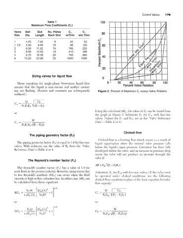
           ing nor flashing. (Factors and constants are subsequently   Figure 2. Percent of Maximum C v versus Valve Rotation.
           outlined.)

                  Q       G F
           C v =
                         P - )
               NF E R   ( 1  P 2
                   P
                 1
                                                                 Using the calculated RE V , the value of F R can be found from
           or
                                                                 the graph in Figure 3. Substitute F L for F LP with line-size
                                                                 valves. (Values for F L and F LP are in the “Valve Reference
                      W
           C v =                                                 Data”—Table 2 or 4.)
                        P - )g
                 6
                   PR
               NF F ( 1    P 2
                                                                                    Choked flow
                     The piping geometry factor (F P )
                                                                   Choked flow is a limiting flow which occurs as a result of
             The piping geometry factor (F P ) is equal to 1.0 for line-size  liquid vaporization when the internal valve pressure falls
           valves. With reducers, use the value of F P from the “Valve  below the liquid’s vapor pressure. Cavitation has then fully
           Reference Data”—Table 2 or 4.                         developed within the valve, and an increase in pressure drop
                                                                 across the valve will not produce an increase through the
                                                                 valve if:
                    The Reynold’s number factor (F R )
                                                                        2
                                                                 DP ≥  F LP ( 1  F P V )
                                                                         P -
                                                                              F
             The Reynold’s number factor (F R ) has a value of 1.0 for
           most flows in the process industry. However, sizing errors due  (Substitute F L for F LP with line-size valves.) If the valve must
           to low Reynold’s numbers (RE V ) can occur when the fluid   be operated under choked conditions, use the following
           viscosity is high or flow velocities low. In either case, RE V can  choked-flow equations in place of the basic equation for valve
           be calculated from these equations:                   flow capacity:
                                      .
                   NW     ( È  FCv) 2  ˘  025                          Q       G F
                    3
                            LP
           RE V =        Í        + ˙ 1                          C v =
                    FCv  Î  ND 4    ˚                                NF LP  ( 1  F P )
                                                                             P -
                                                                       1
                                                                                  FV
                             2
                    LP
           or                                                    or
                                      .
                   NQ     ( È  FCv) 2  ˘ 025                                 W
                     4
                            LP
           RE V =        Í        + ˙ 1                          C V =
                    FCv  Î  ND 4    ˚                                 NF LP ( 1  F P V )g
                                                                             P -
                                                                                 F
                                                                       6
                             2
                     LP
   187   188   189   190   191   192   193   194   195   196   197