
Page 189 - Pipeline Rules of Thumb Handbook
P. 189
176 Pipeline Rules of Thumb Handbook
The reason this is considered a system analysis method is actual tested values may be significantly higher or lower than
because it takes into account the entrance conditions from the 1.5.
vessel to the discharge piping, 8 pipe diameters of piping to
the rupture disc, and 5 pipe diameters of piping, from the
rupture disc to the atmosphere.
The resistance to flow method (K R ) is used if neither of the
first two methods apply, such as systems with long runs of Fitting K
piping, or discharging into manifolds, or flare systems. The
Globe valve, open 9.7
resistance to flow method is not a rupture disc sizing
method, but a system sizing method. This analysis takes into
Angle valve, open 4.6
account the resistance to flow of all of the elements within
the relieving system, including the resistance of the rupture Swing check valve, open 2.3
disc. The Code then requires that the system capacity then
be derated by a factor of 0.9 to account for uncertainties in 90 degree mitered elbow 1.72
the method.
The code does not describe the detailed analysis method, Rupture disc 1.5
other than to say “accepted engineering practices.” Com-
monly used references for this type of analysis are: API RP521 Welded tee flowing through branch 1.37
Guide for Pressure Relieving, and Depressuring Systems of
Crane Paper 410. 15 feet of 3≤ sch 40 pipe 1.04
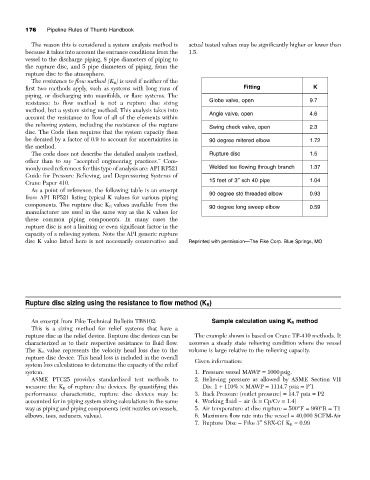
As a point of reference, the following table is an excerpt
from API RP521 listing typical K values for various piping 90 degree std threaded elbow 0.93
components. The rupture disc K R values available from the 90 degree long sweep elbow 0.59
manufacturer are used in the same way as the K values for
these common piping components. In many cases the
rupture disc is not a limiting or even significant factor in the
capacity of a relieving system. Note the API generic rupture
disc K value listed here is not necessarily conservative and Reprinted with permission—The Fike Corp. Blue Springs, MO
Rupture disc sizing using the resistance to flow method (K R )
An excerpt from Fike Technical Bulletin TB8102: Sample calculation using K R method
This is a sizing method for relief systems that have a
rupture disc as the relief device. Rupture disc devices can be The example shown is based on Crane TP-410 methods. It
characterized as to their respective resistance to fluid flow. assumes a steady state relieving condition where the vessel
The K R value represents the velocity head loss due to the volume is large relative to the relieving capacity.
rupture disc device. This head loss is included in the overall
Given information:
system loss calculations to determine the capacity of the relief
system. 1. Pressure vessel MAWP = 1000psig.
ASME PTC25 provides standardized test methods to 2. Relieving pressure as allowed by ASME Section VII
measure the K R of rupture disc devices. By quantifying this Div. 1 + 110% ¥ MAWP = 1114.7 psia = P¢1
performance characteristic, rupture disc devices may be 3. Back Pressure (outlet pressure) = 14.7 psia = P2
accounted for in piping system sizing calculations in the same 4. Working fluid - air (k = Cp/Cv = 1.4)
way as piping and piping components (exit nozzles on vessels, 5. Air temperature at disc rupture = 500°F = 960°R = T1
elbows, tees, reducers, valves). 6. Maximum flow rate into the vessel = 40,000 SCFM-Air
7. Rupture Disc - Fike 3≤ SRX-GI K R = 0.99