
Page 228 - Pipeline Rules of Thumb Handbook
P. 228
Corrosion/Coatings 215
I r uate the requirements for protection against HVDC effects
V =
2 p r in an actual situation.
Figure 3 shows the range or envelope of effects as the
This relationship shows a simplified representation of what HVDC varies from its maximum value in one polarity to the
actually occurs. The earth’s resistivity is not uniform at all maximum value of the other polarity. The coordinates on this
depths or horizontal distances, which causes irregularities to graph are DISTANCE along the X axis and VOLTAGE on the
the ideal voltage distribution existing around an electrode in Y axis.
a homogeneous earth. The voltage corresponds to the effect which would usually
To refine the earth current analysis and to account for dif- be measured on an actual pipeline: pipe-to-soil voltage mea-
ferent resistivities, computer techniques have been developed sured with a copper-copper sulfate half-cell. The value of
to estimate the earth’s gradients existing for conditions of the voltage effect at any point on the line is the product of
multi-layers of earth of different resistivities. Pipeline effects the current transfer, and the electrical resistance between the
have also been predicted by this method. Reasonable agree- pipe material and earth over the same area.
ment between these models and field data has been reported. Figure 3 also shows reasonable hypothetical scale values
Techniques are available to calculate the quantitative charac- illustrating the various combinations of protection require-
teristics of both the earth’s gradient and HVDC effects on ments which may exist in an actual installation. The volt-
pipeline. age values give the change in pipe-to-soil reading that
would be caused by the HVDC transfer current. If this
HVDC is considered as the only source of corrosion, then a
HVDC effects on a pipeline pipe-to-soil voltage reading with a copper-copper sulfate
half-cell would be approximately 0.85 volts at no transfer
Whether the HVDC component of the total current exist-
ing on the line causes a corrosion problem depends on the
level of protection along the line and the effect of the added
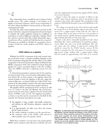
component to the level of protection. Figure 2a illustrates the
HVDC component of the total conducted current along the
pipeline for a given separation distance under the condition
where the HVDC electrode is collecting current from the
earth.
In determining protection requirements for the pipeline,
the characteristic of the current transfer relationship is impor-
tant (Figure 2b). In those regions of the pipeline where the
current transfer is from the pipeline to the soil—along the
center in this case—corrosion could occur if the HVDC com-
ponent of the total transfer current to the soil is great enough
to exceed any local level of protection against corrosion.
The pipeline HVDC arrangement shown in Figure 2a will
serve as a basis to develop and illustrate the performance
requirements for protecting a pipeline from the detrimental
effects of HVDC earth currents. The hypothetical problem,
as shown, is one that may be encountered in the field. In this
example, the following assumptions are made:
• The pipeline is long, straight, electrically continuous,
and uniform in wall thickness, diameter, material and
coating.
• It is approximately 30 miles away from the nearest
HVDC earth electrode. Figure 2. (a) Geometric plan between the HVDC electrode and
• The earth’s resistivity is uniform over the general area. the pipeline. Arrows indicate the direction of the HVDC compo-
• The maximum value of the HVDC earth current in nent current. These would be reversed if the polarity of the elec-
either polarity causes the pipeline effects. trode were reversed. (b) Curve shows characteristics of the
transfer of HVDC into and out of the pipeline along its length.
The transfer current is equivalent to current density. (c) Con-
While these conditions may not exist in any actual pipeline ducted current in the pipeline which results in the summation of
HVDC system situation, they will serve to identify and eval- the transfer current along the pipe.