
Page 229 - Pipeline Rules of Thumb Handbook
P. 229
216 Pipeline Rules of Thumb Handbook
current. This scale is shown on the left side of the figure. Cor- disbonding limit. The difference between these limits gives
rosion occurs for any reading below this axis, since the current an assumed safe operating band width of 0.65 volts.
is leaving the pipeline and entering the soil to cause this Values other than these may be used for specific applica-
change in the pipe-to-soil reading. tions. These limits, however, will serve to illustrate the
At locations on the pipeline where HVDC causes con- principles.
ditions which increase the volt-meter reading, current is col-
lecting on the pipeline. The horizontal axis, therefore,
represents a corrosion limit. Above this axis, a coating dis- Protective system limits
bonding limit can exist where the density of the current trans-
ferred from the earth to the pipeline causes gas evolution, The requirements for protection along the line from either
which may blister the coating. corrosion or disbonding are developed from examination of
In this example, a pipe-to-soil reading with a copper- Figure 3 and the results are plotted in the subsequent figures.
copper sulfate half-cell of 1.5 volts is shown as the coating The upper limit of protection is the maximum amount of
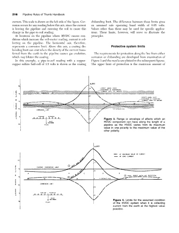
Figure 3. Range or envelope of effects which an
HVDC component can have along the length of a
pipeline as the HVDC varies from its maximum
value in one polarity to the maximum value of the
other polarity.
Figure 4. Limits for the assumed condition
of the HVDC system when it is collecting
current from the earth at the highest value
possible.