
Page 231 - Pipeline Rules of Thumb Handbook
P. 231
218 Pipeline Rules of Thumb Handbook
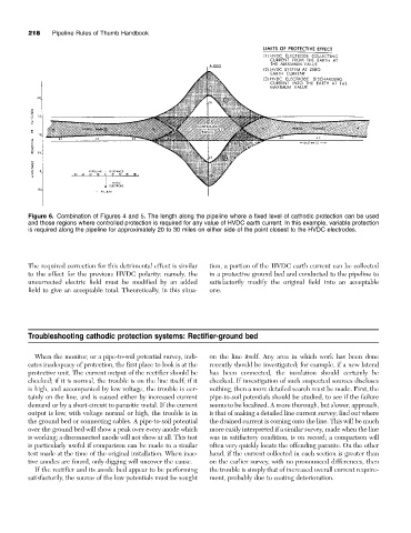
Figure 6. Combination of Figures 4 and 5. The length along the pipeline where a fixed level of cathodic protection can be used
and those regions where controlled protection is required for any value of HVDC earth current. In this example, variable protection
is required along the pipeline for approximately 20 to 30 miles on either side of the point closest to the HVDC electrodes.
The required correction for this detrimental effect is similar tion, a portion of the HVDC earth current can be collected
to the effect for the previous HVDC polarity: namely, the in a protective ground bed and conducted to the pipeline to
uncorrected electric field must be modified by an added satisfactorily modify the original field into an acceptable
field to give an acceptable total. Theoretically, in this situa- one.
Troubleshooting cathodic protection systems: Rectifier-ground bed
When the monitor, or a pipe-to-soil potential survey, indi- on the line itself. Any area in which work has been done
cates inadequacy of protection, the first place to look is at the recently should be investigated; for example, if a new lateral
protective unit. The current output of the rectifier should be has been connected, the insulation should certainly be
checked; if it is normal, the trouble is on the line itself; if it checked. If investigation of such suspected sources discloses
is high, and accompanied by low voltage, the trouble is cer- nothing, then a more detailed search must be made. First, the
tainly on the line, and is caused either by increased current pipe-to-soil potentials should be studied, to see if the failure
demand or by a short-circuit to parasitic metal. If the current seems to be localized. A more thorough, but slower, approach,
output is low, with voltage normal or high, the trouble is in is that of making a detailed line current survey; find out where
the ground bed or connecting cables. A pipe-to-soil potential the drained current is coming onto the line. This will be much
over the ground bed will show a peak over every anode which more easily interpreted if a similar survey, made when the line
is working; a disconnected anode will not show at all. This test was in satifactory condition, is on record; a comparison will
is particularly useful if comparison can be made to a similar often very quickly locate the offending parasite. On the other
test made at the time of the original installation. When inac- hand, if the current collected in each section is greater than
tive anodes are found, only digging will uncover the cause. on the earlier survey, with no pronounced differences, then
If the rectifier and its anode bed appear to be performing the trouble is simply that of increased overall current require-
satisfactorily, the source of the low potentials must be sought ment, probably due to coating deterioration.