
Page 68 - Pipeline Rules of Thumb Handbook
P. 68
Construction 55
or relocated so that bicycles, becaks, and water buffalo would Construction
have easier access.
It was determined that 4ft of cover was required to protect The design package to the field should include drawing
the line from excessive wheel loads (people-packed buses and of new profiles, stations, tables of new pipeline elevations,
trucks). This means the line must be lowered 7ft (Figure 1). trench elevations, and a very detailed construction se-
The pipe is Grade B, allowable bending stress is 10,000psi, quence. The following may be used as a guide for construc-
and crossing width is 50ft. To calculate minimum bending tion:
radius, total transition length, and deflections at 25-ft inter-
vals, use: • Starting at one end of transition, dig 40ft of trench under
the line. Leave 10ft of soil for pipe support. Dig another
)( )
¢
,
REC S = (29 000 000 18 10 000 = 52 200 in. 40ft, repeat until opposite end is reached. When com-
,
,
=
,
,
= 4 350 ft (min. ) plete, 10-ft soil plugs are supporting the line at 50-ft
centers.
Total transition length = ()+ 50 ft
4
X
• Clean the line between soil supports, take ultrasonic
Y = 70 . ft 2 = 3 5 . ft test (UT) readings, and install sleeve where required.
-
X = 2 RY Y 2 Add primer and tape wrap between supports, main-
taining station numbers and elevation points on the
2
X = ()(4 350 )(3 5 . ) -(3 5 . ) = 175 ft line.
,
2
Total transition length = 750 ft • Add 12in. of sand or soil/sand pre-mix to bottom of
trench and compact to proper trench bottom elevation
It is suggested that field personnel start survey (elevations) (profile elevation minus pipeline diameter).
500ft left of crossing centerline and stop at station 10 + 00. • Install 6-in. ¥ 6-in. wooden blocks every 50ft (between
Deflections at 25-ft intervals are calculated from Eq. 3 soil plugs) to support the line.
(Figure 3), and a table is prepared accordingly (Table 1). Note • Remove soil plugs and complete line cleaning, UT
that calculations for Y are required for 175ft only. Since the readings, sleeve installations, tape wrapping, and trench
curve is then inverted (Sta 3 + 00 to Sta 4 + 75), results are preparation.
subtracted from 7.0ft, working backwards, to arrive at true • Check elevations of new trench bottom, adjust as
deflection or drop. For example, deflection at Sta 4 + 50 = 7.0 required. Check tape wrap with holiday detector if
- 0.07 = 6.93, etc. desired.
• Starting at one end, use six sidebooms to raise approxi-
Example 2. Given following elevations, is pipeline being mately 250ft of line off its supports. Remove 6in. (or less)
dropped too suddenly, and will it become over-stressed of blocks on outside supports and 12in. of blocks on all
between stations 1 + 00 and 1 + 50 (Figure 2)? inner supports. Lower line onto supports.
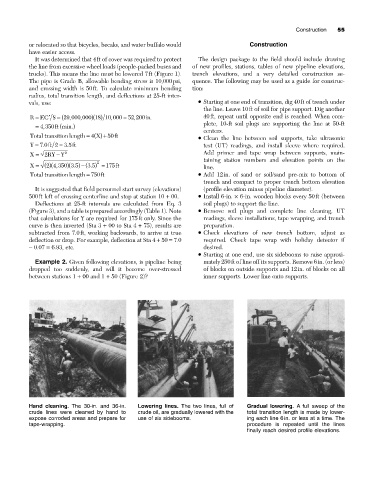
Hand cleaning. The 30-in. and 36-in. Lowering lines. The two lines, full of Gradual lowering. A full sweep of the
crude lines were cleaned by hand to crude oil, are gradually lowered with the total transition length is made by lower-
expose corroded areas and prepare for use of six sidebooms. ing each line 6in. or less at a time. The
tape-wrapping. procedure is repeated until the lines
finally reach desired profile elevations.