
Page 67 - Pipeline Rules of Thumb Handbook
P. 67
54 Pipeline Rules of Thumb Handbook
For instance, in Saudi Arabia, an extensive highway mod-
ernization program resulted in scores of large-diameter
pipelines being lowered. A few line sections ruptured during
the pioneer stages due to the fact that each situation was
not properly evaluated in terms of a critical engineering
problem.
The key to the problem’s solution is to provide a smooth
profile with constant radius bends and to include a detailed
list of instructions with the design package. Careful monitor-
ing by survey equipment (levels) will assure smooth transi-
tions in the field.
The following approach has been used effectively on
numerous occasions in Saudi Arabia and Indonesia and can
be recommended. Design steps to be included are:
• Determine how much soil cover there should be over the
top of pipeline to assure protection from construction
equipment and wheel loads (see API-RP-1102). Four
feet of cover is adequate for pipelines 12in. and smaller.
Larger pipelines may require additional protection by
way of more cover, pipe sleeves, or concrete slabs.
• Determine allowable bending stress on pipeline, based
on grade of pipe. Normally, 75% of allowable stress is
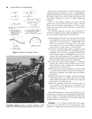
Figure 3. Formulas for changes in slope. acceptable for cross-country pipelines (ANSI B31.4,
Section 419.6). However, 10,000-psi stress is very con-
servative and often preferred. If the pipeline is com-
pletely restrained (anchors on each end and no expansion
loops), thermal stresses must also be considered.
• Once the total required drop of pipeline is established,
calculate the minimum bending radius based on allow-
able bending stress. Then calculate the overall transition
length from one end to the other.
• Obtain elevations on top of the pipeline every 25ft (Table
1), marking station numbers and elevations with paint. If
the line is on supports, also include grade elevations at
each station.
• Starting at each end of transition, calculate the drop at
25-ft stations. Draw up a profile and fit it on existing
profile. Add stations and new elevations (top of pipe and
trench bottom) to profile drawing.
• Check the transition points at the beginning and end
of new profile. If the pipeline was going uphill, and
suddenly it needs to go downhill, the end points may be
critical in terms of stress.
Since any three points not on the same line form an arc of
constant radius, the stress may be approximated by Equations
7 and 4 (Figure 3). The end point should become the center
of three points for calculation. If over-stressed, widen the
transition length and check again.
Example 1. A new village was being built in the jungle,
Excavation begins. Ten-foot soil plugs remained at 50-ft but access was obstructed by an above-ground, 36-in.
centers to act as temporary pipe supports for the 36-in. line. pipeline. The village head requested that the line be buried