
Page 66 - Pipeline Rules of Thumb Handbook
P. 66
Construction 53
PIPE LOWERING
How to lower an existing pipeline that is still in service
Lowering a loaded pipeline is a low-cost alternative for constructing new facilities
Marshall D. Cromwell, Senior Project Engineer, PT Caltex Pacific Indonesia, Jakarta, Indonesia
Lowering an existing line is a dirty little job, but it can have
big cost benefits. The line can be lowered while remaining in
service with no lost production, and the cost of lowering an
existing pipeline section is relatively cheap.
No expenses are incurred for new pipe, valves, stopples,
and fittings. Construction is much faster than cutting and
relocating a pipeline section.
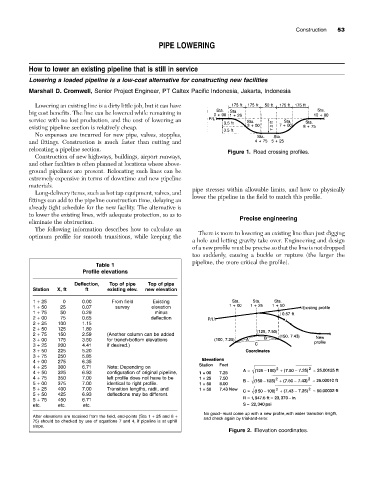
Figure 1. Road crossing profiles.
Construction of new highways, buildings, airport runways,
and other facilities is often planned at locations where above-
ground pipelines are present. Relocating such lines can be
extremely expensive in terms of downtime and new pipeline
materials. pipe stresses within allowable limits, and how to physically
Long-delivery items, such as hot tap equipment, valves, and
fittings can add to the pipeline construction time, delaying an lower the pipeline in the field to match this profile.
already tight schedule for the new facility. The alternative is
to lower the existing lines, with adequate protection, so as to
Precise engineering
eliminate the obstruction.
The following information describes how to calculate an
optimum profile for smooth transitions, while keeping the There is more to lowering an existing line than just digging
a hole and letting gravity take over. Engineering and design
of a new profile must be precise so that the line is not dropped
too suddenly, causing a buckle or rupture (the larger the
pipeline, the more critical the profile).
Table 1
Profile elevations
Deflection, Top of pipe Top of pipe
Station X, ft ft existing elev. new elevation
1 + 25 0 0.00 From field Existing
1 + 50 25 0.07 survey elevation
1 + 75 50 0.29 minus
2 + 00 75 0.65 deflection
2 + 25 100 1.15
2 + 50 125 1.80
2 + 75 150 2.59 (Another column can be added
3 + 00 175 3.50 for trench-bottom elevations
3 + 25 200 4.41 if desired.)
3 + 50 225 5.20
3 + 75 250 5.85
4 + 00 275 6.35
4 + 25 300 6.71 Note: Depending on
4 + 50 325 6.93 configuration of original pipeline,
4 + 75 350 7.00 left profile does not have to be
5 + 00 375 7.00 identical to right profile.
5 + 25 400 7.00 Transition lengths, radii, and
5 + 50 425 6.93 deflections may be different.
5 + 75 450 6.71
etc. etc. etc.
After elevations are received from the field, end-points (Sta 1 + 25 and 8 +
75) should be checked by use of equations 7 and 4, if pipeline is at uphill
slope.
Figure 2. Elevation coordinates.