
Page 62 - Pipeline Rules of Thumb Handbook
P. 62
Construction 49
Average pipelay table—On supports
Linear feet of pipelay per ten (10) hour day on waist-high supports on level ground
PIPE WALL THICKNESS IN INCHES
Nominal 0.000 0.251 0.376 0.501 0.626 0.756
Pipe through through through through through through
Size 0.250 0.375 0.500 0.625 0.750 1.000
4 11,320 11,100 10,880 — — —
6 10,080 9,880 9,680 — — —
8 9,560 9,370 9,190 9,010 — —
10 9,390 9,200 9,020 8,840 — —
12 8,800 8,620 8,500 8,330 8,160 —
14 8,700 8,570 8,400 8,250 8,090 —
16 8,040 7,880 7,730 7,580 7,430 7,280
18 7,800 7,650 7,500 7,350 7,200 7,060
20 7,550 7,400 7,250 7,100 6,960 6,820
24 — 6,720 6,590 6,460 6,330 6,200
30 — 6,120 6,000 5,880 5,770 5,660
36 — — 5,440 5,350 5,240 5,140
42 — — 4,840 4,740 4,650 4,560
Productivity will vary with contour of terrain and accessibility.
Above footage is based on installing double random joints of pipe.
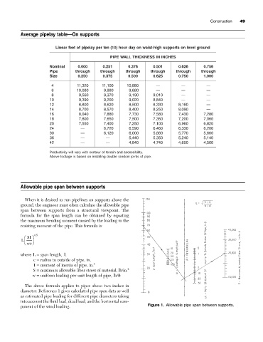
Allowable pipe span between supports
When it is desired to run pipelines on supports above the
ground, the engineer must often calculate the allowable pipe
span between supports from a structural viewpoint. The
formula for the span length can be obtained by equating
the maximum bending moment caused by the loading to the
resisting moment of the pipe. This formula is:
05
.
Ê SI ˆ
L
Ë wc ¯
where L = span length, ft
c = radius to outside of pipe, in.
I = moment of inertia of pipe, in. 4
S = maximum allowable fiber stress of material, lb/in. 2
w = uniform loading per unit length of pipe, lb/ft
The above formula applies to pipes above two inches in
diameter. Reference 1 gives calculated pipe span data as well
as estimated pipe loading for different pipe diameters taking
into account the fluid load, dead load, and the horizontal com-
ponent of the wind loading. Figure 1. Allowable pipe span between supports.