Page 65 - Pipeline Rules of Thumb Handbook
P. 65

52    Pipeline Rules of Thumb Handbook

                                                               positive and the tangent ahead is greater positive slope, a sag
                                                               is noted. The reverse holds true for change in negative slope:
                                                               if the tangent ahead is increasing, the transition is an over-
                                                               bend; if it is decreasing, the transition is a sag. The unlike
                                                               algebraic signs are added and like signs are subtracted. Figure
                                                               2, station 2 + 00, shows a positive 10° slope approaching the
                                                               overbend and a negative 1° slope leaving it. Since the signs
                                                               are unlike, the sum of the two angles is 11° and since the slope
                                                               is positive and decreasing, the notation overbend is used.


                                                                                Side bend angles

                                                                 Side bends are determined by “eyeballing” a P.I. in the
                                                               ditch and setting the instrument up over it. A back sight is
                                                               taken on the ditch or preceding P.I., whichever is more easily
                                                               read. The scope is flipped and a foresight is taken on the ditch
                               Figure 3
                                                               ahead. Referring to Figure 2 at station 1 + 00, the deflection
                                                               angle is 6° left; station 4 + 00 shows a deflection of 8° right.
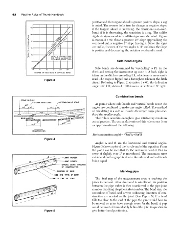

                                                                               Combination bends

                                                                 At points where side bends and vertical bends occur the
                                                               angles are combined to make one angle rolled. The method
                                                               of calculating is a rule of thumb: the larger angle plus one-
                                                               third the smaller angle.
                                                                 This rule is accurate enough to give satisfactory results in
                                                               actual practice. The actual derivation of this rule comes from
                                                               an approximation of the following:


                                                                  (
                                                                                               2
                                                                                         2
                                                                                           +
                                                                   Sin combination angle) =  Sin A Sin B
                               Figure 4
                                                                 Angles A and B are the horizontal and vertical angles.
                                                                                      1
                                                               Figure 3 shows a plot of the  / 3 rule and of the equation. From
                                                               the plot it can be seen that for the maximum bend of 18.5 an
                                                               error of slightly over 1° is introduced. The maximum error
                                                               evidenced on the graph is due to the side and vertical bends
                                                               being equal.


                                                                                  Marking pipe

                                                                 The final step of the measurement crew is marking the
                                                               joints to be bent. After the bend is established, its position
                                                               between the pipe stakes is then transferred to the pipe joint
                                                               number matching the pipe stakes number. The bend size, the
                                                               centerline of bend, and arrows indicating direction of con-
                                                               struction are marked on the joint. (See Figure 5.) If a bend
                                                               falls too close to the end of the pipe the joint would have to
                                                               be moved, so as to leave enough room for the bend. A pup
                                                               could be inserted immediately behind the joint in question to
                               Figure 5                        give better bend positioning.
   60   61   62   63   64   65   66   67   68   69   70