
Page 76 - Pipeline Rules of Thumb Handbook
P. 76
Construction 63
ONE OF THE PRIME OBJECTIVES OF THE STRINGER BEAD CREW SHOULD BE TO PROVIDE A GOOD,
STOUT STRINGER WITH AS MUCH THROAT AS POSSIBLE.
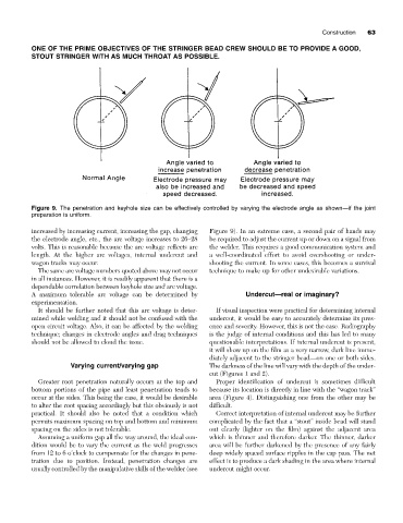
Figure 9. The penetration and keyhole size can be effectively controlled by varying the electrode angle as shown—if the joint
preparation is uniform.
increased by increasing current, increasing the gap, changing Figure 9). In an extreme case, a second pair of hands may
the electrode angle, etc., the arc voltage increases to 26–28 be required to adjust the current up or down on a signal from
volts. This is reasonable because the arc voltage reflects arc the welder. This requires a good communication system and
length. At the higher arc voltages, internal undercut and a well-coordinated effort to avoid overshooting or under-
wagon tracks may occur. shooting the current. In some cases, this becomes a survival
The same arc voltage numbers quoted above may not occur technique to make up for other undesirable variations.
in all instances. However, it is readily apparent that there is a
dependable correlation between keyhole size and arc voltage.
A maximum tolerable arc voltage can be determined by Undercut—real or imaginary?
experimentation.
It should be further noted that this arc voltage is deter- If visual inspection were practical for determining internal
mined while welding and it should not be confused with the undercut, it would be easy to accurately determine its pres-
open circuit voltage. Also, it can be affected by the welding ence and severity. However, this is not the case. Radiography
technique; changes in electrode angles and drag techniques is the judge of internal conditions and this has led to many
should not be allowed to cloud the issue. questionable interpretations. If internal undercut is present,
it will show up on the film as a very narrow, dark line imme-
diately adjacent to the stringer bead—on one or both sides.
Varying current/varying gap The darkness of the line will vary with the depth of the under-
cut (Figures 1 and 2).
Greater root penetration naturally occurs at the top and Proper identification of undercut is sometimes difficult
bottom portions of the pipe and least penetration tends to because its location is directly in line with the “wagon track”
occur at the sides. This being the case, it would be desirable area (Figure 4). Distinguishing one from the other may be
to alter the root spacing accordingly but this obviously is not difficult.
practical. It should also be noted that a condition which Correct interpretation of internal undercut may be further
permits maximum spacing on top and bottom and minimum complicated by the fact that a “stout” inside bead will stand
spacing on the sides is not tolerable. out clearly (lighter on the film) against the adjacent area
Assuming a uniform gap all the way around, the ideal con- which is thinner and therefore darker. The thinner, darker
dition would be to vary the current as the weld progresses area will be further darkened by the presence of any fairly
from 12 to 6 o’clock to compensate for the changes in pene- deep widely spaced surface ripples in the cap pass. The net
tration due to position. Instead, penetration changes are effect is to produce a dark shading in the area where internal
usually controlled by the manipulative skills of the welder (see undercut might occur.