
Page 510 - Pipelines and Risers
P. 510
LCC Modeling as a Decision Making Tool in Pipeline Design 477
Corrosion rate (CR) is based on De Waard '93 formula. This gives corrosion rate as a function
of temperature, pressure and Cot content. In addition, effects due to pH, saturation of
corrosion products, glycol content and scale formation may be accounted for.
The following assumptions are made:
0 The corrosion rate during normal operation is negligible;
Corrosion will only occur following an upset where water or wet gas is introduced into the
line. The time during which corrosion can occur is labeled tw (= total duration of wet
service). The determination of tw is described in Step 5,
0 Glycol will be present in the line as a continuous film on the pipe wall because of carry-
over from the glycol drying unit. The water ingress in the line will thus result in an
increased water content in the glycol film. The water content in the glycol film is assumed
to increase to a maximum of 50% following an upset.
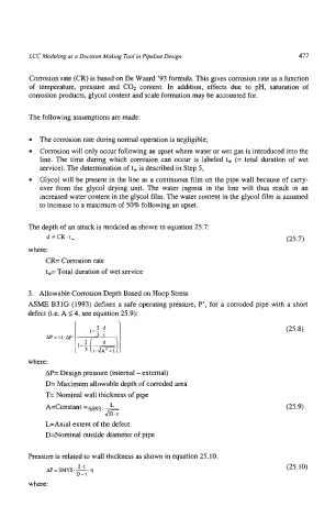
The depth of an attack is modeled as shown in equation 25.7:
d=CR.t, (25.7)
where:
CR= Corrosion rate
t+ Total duration of wet service
3. Allowable Corrosion Depth Based on Hoop Stress
ASME B31G (1993) defines a safe operating pressure, P', for a corroded pipe with a short
defect (i.e. A 14, see equation 25.9):
(25.8)
where:
AI'= Design pressure (internal - external)
D= Maximum allowable depth of corroded area
T= Nominal wall thickness of pipe
A=Constant =O.g93. - L (25.9)
fi
LsAxial extent of the defect
D=Nominal outside diameter of pipe
Pressure is related to wall thickness as shown in equation 25.10.
AP = SMYS .-. 2.t tl (25.10)
D-t
where: