
Page 512 - Pipelines and Risers
P. 512
LCC Modeling m a Decision Making Tool in Pipeline Design 479
The limit state functions used for the corrosion allowance calculations are shown in equations
25.14 and 25.15.
(25.14)
- CR ._ tw
365
where:
x,= Corrosion rate model uncertainty factor
XF Wall thickness uncertainty factor (from manufacturing process)
(25.15)
Note that the expression for g2 is somewhat simplified for clarity. In the analysis, the equation
2.20 is solved for pc with h as given in equation 25.16.
h=t-CR.x, .k (25.16)
365
In addition, the expression for wall thickness, t, in the limit state function, is always
multiplied with it's uncertainty factor, xt, and M, is calculated from equation 3.47.
25.5.7 Step 5- Definition of Parameters and Variables
1. Pipeline, Operational and Environmental Data
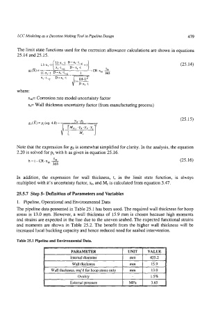
The pipeline data presented in Table 25.1 has been used. The required wall thickness for hoop
stress is 13.0 mm. However, a wall thickness of 15.9 mm is chosen because high moments
and strains are expected in the line due to the uneven seabed. The expected functional strains
and moments are shown in Table 25.2. The benefit from the higher wall thickness will be
increased local buckling capacity and hence reduced need for seabed intervention.
Table 25.1 Pipeline and Environmental Data.