
Page 224 - Planning and Design of Airports
P. 224
Geometric Design of the Airfield 189
N
NNW NNE
NW 0.5 NE
0.1
0.1 1.0 0.4
0.4
0.2 0.9 1.2 1.0
WNW ENE
0.6 1.6
0.2 1.7 2.4 3.0 0.1
0.6 1.7 5.3 3.1 1.7
3.8 6.8
W 0.1 0.4 4.9 8.1 7.1 2.3 1.9 0.2 E
2.7 6.4
0.4 1.5 5.8 3.5
0.1 1.7 3.8 1.9
1.8
0.6 1.9 0.1
WSW 0.2 0.8 1.0 1.1 ESE
0.4
0.4 0.1
0.1
SW 0.3 SE
SSW SSE
S
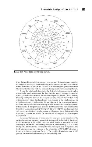
FIGURE 6-8 Wind data in wind rose format.
from that used in numbering runways since runway designations are based on
the magnetic bearing. As illustrated in Fig. 6-9, a runway oriented on an azimuth
to true north of 90° to 270° (N 90° E to S 90° W true bearing) will permit operations
90.8 percent of the time with the crosswind components not exceeding 15 mi/h.
Should the wind analysis not give the desired wind coverage, the template
may then be used to determine the direction of a second runway, a crosswind
runway, which would increase the wind coverage to 95 percent. This is done by
blocking out the area between the two outer parallel lines for the direction of the
primary runway (since this has already been counted in the wind coverage for
the primary runway) and rotating the template until the percentages between
the outer parallel lines for the remaining area for another direction is maximized.
If this is done in this problem it is found that the crosswind runway should be
located in an orientation of 12° to 192° (N 12° E to S 12° W true bearing). This
will permit an additional wind coverage of 6.2 percent above that provided by
the runway oriented 90° to 270° for a total wind coverage for both runways of
97.0 percent.
Let us say that because of noise-sensitive land uses in the direction of the
optimal crosswind runway, a crosswind runway will be located at the airport
in the orientation of 30° to 210° direction which results in an additional wind
coverage of 5.8 percent. This runway orientation, called runway 3–21, is shown
in Fig. 6-10. The total wind coverage for both runways is then 96.6 percent. The
total wind coverage for a runway in the orientation of 30° to 210° direction is
found to be 84.8 percent from Fig. 6-11. The combined wind coverage of 96.6
percent for the use of either runway is shown in Fig. 6-11.